Photovoltaic system having fault diagnosis apparatus, and fault diagnosis method for photovoltaic system

a photovoltaic system and fault diagnosis technology, applied in the direction of photovoltaic monitoring, ac network circuit arrangement, semiconductor devices, etc., can solve the problems of difficult to determine whether or not the system has faults, difficult to check solar module faults (short-circuit, disconnection, etc.) by naked eye, etc., to achieve easy detection, easy to determine, and low initial investment cost

Active Publication Date: 2017-03-02
KOREA INST OF ENERGY RES
View PDF0 Cites 16 Cited by
  • Summary
  • Abstract
  • Description
  • Claims
  • Application Information

AI Technical Summary

Benefits of technology

[0016]According to the present invention, the temperature sensor and the voltage sensor are provided in the junction box such that initial investment costs can be inexpensive. In addition, the solar module faults, which are difficult to be determined by the naked eye, can be easily determined, and the inverter and bypass diode faults can be easily detected. Therefore, costs, time, efforts for operating and maintaining the photovoltaic system can be remarkably reduced. In addition, durability of the photovoltaic system can be remarkably enhanced.

Problems solved by technology

The greenhouse effect caused by excessive use of fossil fuels has become a serious problem.
However, it is difficult to check solar module faults (short-circuit, disconnection, etc.) by naked eye.
Furthermore, in spite of monitoring voltage, current, power of each string at an end of an inverter, when some of the solar cells do not operate, it is difficult to determine whether or not the system has faults due to operation of a bypass diode.
In addition, it is particularly difficult to check inverter faults or bypass diode faults because results of the faults are similar to results of the solar module faults.
Furthermore, the inverter faults or the bypass diode faults cause an increase in temperature of the solar modules, and thus, the solar modules will have great deterioration.
However, excessive initial investment costs are required.
The monitoring system determines the solar module has a tracking error when a temperature value detected by the temperature detecting unit is beyond a preset range.
Therefore, the fault diagnosis is unable to detect solar cell faults, etc.

Method used


Image

  • Photovoltaic system having fault diagnosis apparatus, and fault diagnosis method for photovoltaic system
  • Photovoltaic system having fault diagnosis apparatus, and fault diagnosis method for photovoltaic system
  • Photovoltaic system having fault diagnosis apparatus, and fault diagnosis method for photovoltaic system

Examples


Embodiment Construction

[0026]Hereinafter, exemplary embodiments of the present invention will be described in detail with reference to the accompanying drawings. Specific structural and functional descriptions of embodiments of the present invention disclosed herein are only for illustrative purposes of the embodiments of the present invention. The present invention may be embodied in many different forms without departing from the spirit and significant characteristics of the present invention. Therefore, the embodiments of the present invention are disclosed only for illustrative purposes and should not be construed as limiting the present invention.

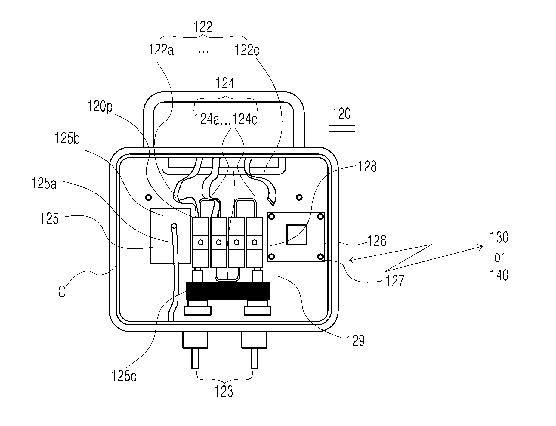
[0027]The present invention relates to a photovoltaic system having a fault diagnosis apparatus, and to a fault diagnosis method for the photovoltaic system. The fault diagnosis method for the photovoltaic system includes a first exemplary embodiment shown in FIG. 5a, and a second exemplary embodiment shown in FIG. 5b. The second exemplary embodiment relates...


PUM


Abstract

The present invention relates to a fault diagnosis for a photovoltaic system. A fault diagnosis apparatus includes a temperature sensor unit measuring both an internal temperature value of the junction box and a surface temperature value of the solar module; a voltage sensor provided in the junction box; and an operation unit determining where a fault occurs among the solar module, an inside of the junction box, and the inverter by comparing measured values of the temperature sensor unit with a measured value of the voltage sensor. According to the present invention, initial investment cost is inexpensive. In addition, it is possible to detect solar module faults that are difficult to be checked by the naked eye.

Description

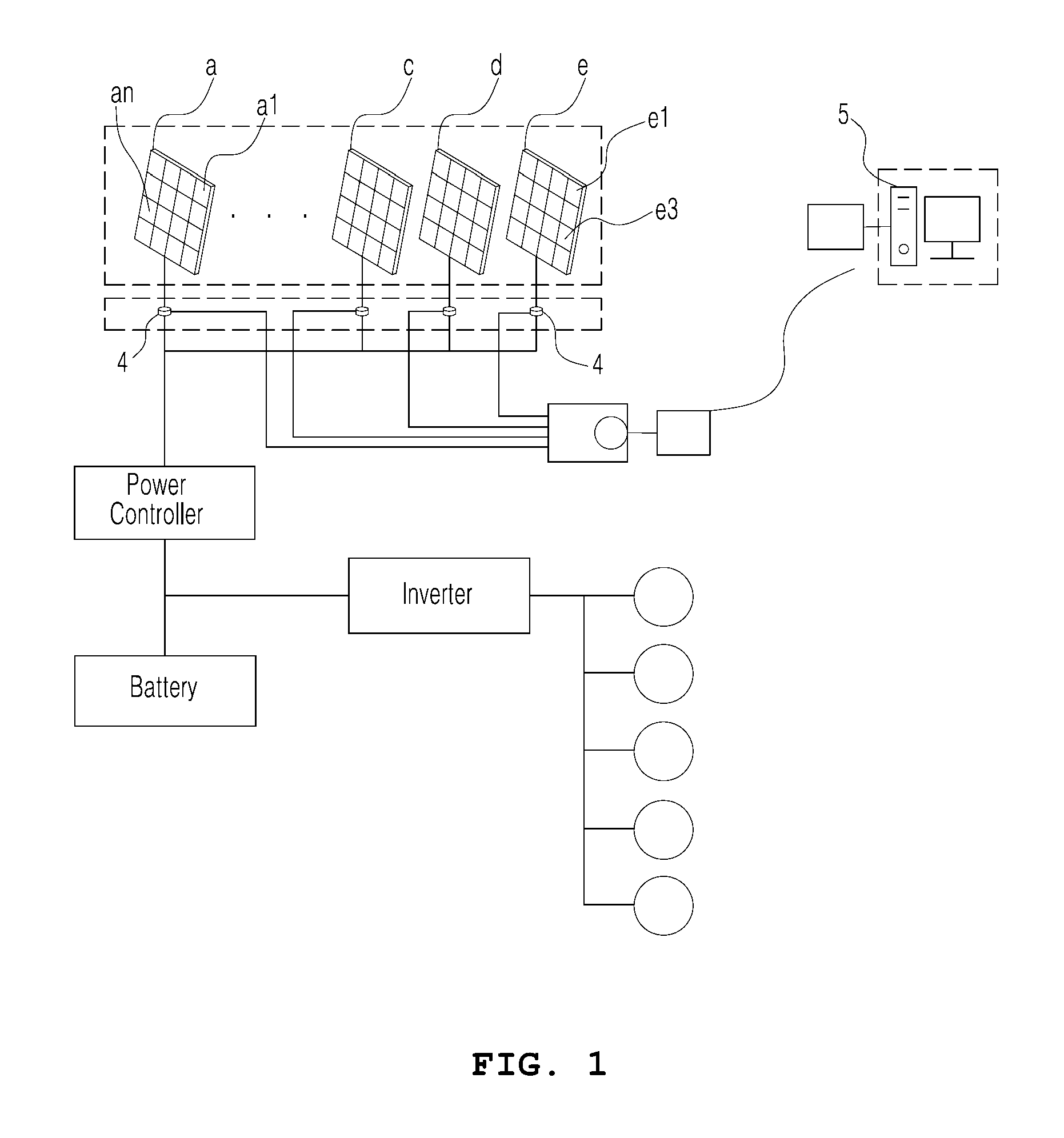
TECHNICAL FIELD[0001]The present invention relates to fault diagnosis for a photovoltaic system. More particularly, it relates to a photovoltaic system having a fault diagnosis apparatus and a fault diagnosis method for the photovoltaic system, the fault diagnosis apparatus determining whether or not the photovoltaic system has a fault by measuring a temperature value and a voltage value of the system.BACKGROUND ART[0002]The greenhouse effect caused by excessive use of fossil fuels has become a serious problem. In order to solve this problem, research into alternative energies is ongoing. Representative examples of alternative energy are wind power, wave power, and solar energy.[0003]Recently, technology for power generation using solar energy has become competitive due to a dissemination of technology related to renewable energy, a decrease in solar cell cost, etc. In addition, the technology is being standardized. FIG. 1 is a view showing an example of a photovoltaic system disclo...

Claims


Application Information

Patent Timeline
Patent Type & Authority Applications(United States)
IPC IPC(8): H02S50/10H02J3/38H01L31/02H02S40/34H02S40/32
CPCH02S50/10H02S40/34H02J3/383H01L31/0201H02S40/32H02J2300/24H02J3/381Y02E10/56H02S50/15
Inventor KO, SUKWHANJUNG, YOUNGSEOKKANG, GI-HWANJU, YOUNGCHULHWANG, HYEMISO, JUNGHUNSONG, HEE-EUN
Owner KOREA INST OF ENERGY RES
Why Eureka
Try Eureka