
High-power bi-directional non-recovery spring magnetic valve comprising permanent magnet

Active Publication Date: 2017-03-16
HARBIN INST OF TECH
View PDF0 Cites 24 Cited by
  • Summary
  • Abstract
  • Description
  • Claims
  • Application Information

AI Technical Summary

Benefits of technology

The present invention provides a high-power bi-directional no-recovery spring electromagnetic valve with a permanent magnet that is symmetrical in structure, simple to assemble, and a bi-stable magnetic latching valve that is adjustable with a flexible counterforce design. The valve has a lower activation condition, is smaller in pull-in(drop-out) ampere turns, has a smaller power, and has the characteristics of a faster response time and a higher output force. The permanent magnet is away from regions where main contacts and an arc extinguish chamber are located, thus reducing adverse effects of high temperatures on the magnet. The structure also has good vibration-resistance, improved assembly effectiveness, enhanced product uniformity, and reduced rejection rate of batch products.

Problems solved by technology

However, traditional electromagnetic valves have disadvantages of a slow response time, a low output force and the like, thus cannot meet industrial production demands under specific circumstances.

Method used


Image

  • High-power bi-directional non-recovery spring magnetic valve comprising permanent magnet
  • High-power bi-directional non-recovery spring magnetic valve comprising permanent magnet
  • High-power bi-directional non-recovery spring magnetic valve comprising permanent magnet

Examples


embodiment 1

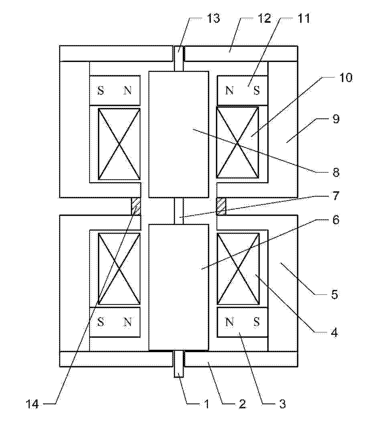
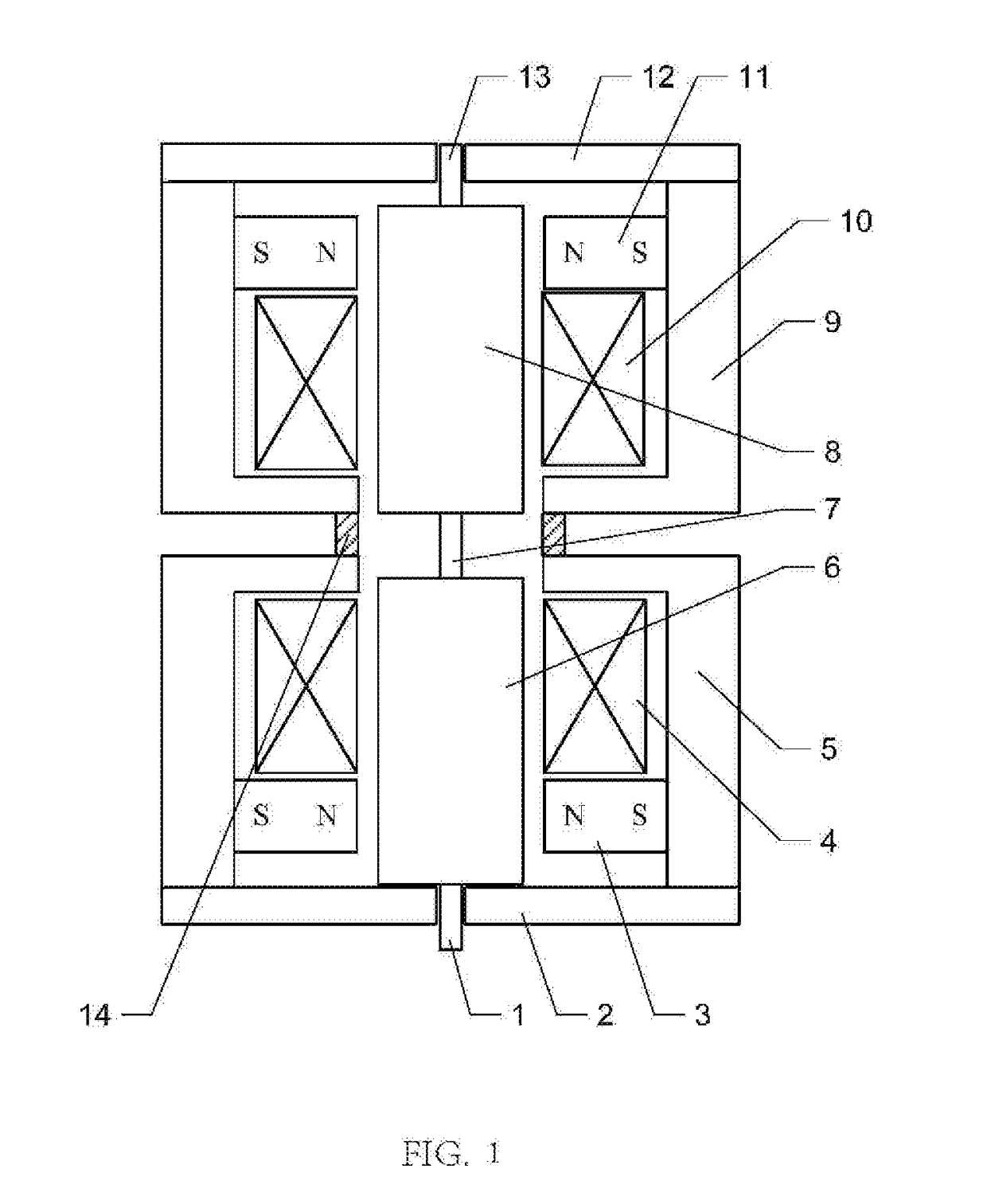
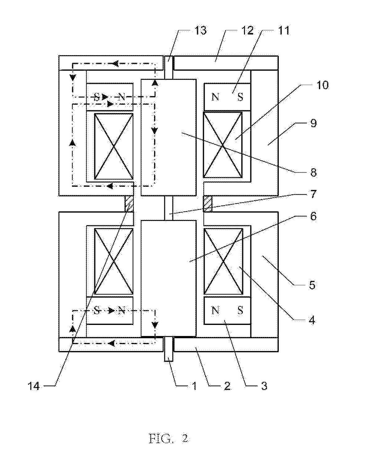
[0019]this embodiment will be explained below with reference to FIGS. 1 to 7. A high-power bi-directional no-recovery spring electromagnetic valve with a permanent magnet of this embodiment comprises an upper magnetic circuit part, a lower magnetic circuit part, an armature connection rod 7 and a housing connection ring 14; wherein, the upper magnetic circuit part and the lower magnetic circuit part are symmetrically disposed, and are connected together via the armature connection rod 7 and the housing connection ring 14;

[0020]the upper magnetic circuit part comprises an upper iron core 8, an upper housing 9, an upper coil 10, an upper annular permanent magnet 11, an upper yoke iron 12 and an upper push rod 13; the upper housing 9 is a cylinder with an upwardly oriented opening; the upper yoke iron 12 is provided on an upper opening of the upper housing 9; and a center hole of the upper yoke iron 12 is used for accommodating the upper push rod 13 to make an up-and-down movement; the...


PUM


Abstract

A high-power bi-directional non-recovery spring magnetic valve including permanent magnets has an upper magnetic circuit part and lower magnetic circuit part symmetrically disposed and connected together via an armature connection rod and a housing connection ring, the upper magnetic circuit part comprises an upper iron core, an upper housing, an upper coil, an upper annular permanent magnet, an upper yoke iron and an upper push rod, the lower magnetic circuit part comprises a lower iron core, a lower housing, a lower coil, a lower annular permanent magnet, a lower yoke iron and a lower push rod. The magnetic valve comprising permanent magnets realizes bistable-state magnetic retaining, and has an adjustable retaining force for permanent magnet adjustment, quick response, and high output force.

Description

FIELD OF THE INVENTION[0001]The present invention relates to a high-power bi-directional no-recovery spring electromagnetic valve with a permanent magnet and belongs to the field of electromagnetic valves. The electromagnetic valve with a permanent magnet specifically refers to an electromagnetic valve comprising a permanent magnet arranged inside.BACKGROUND OF THE INVENTION[0002]The electromagnetic valve is an industrial device for carrying out electromagnetic control, and is a basic automation element for fluid control. The electromagnetic valve belongs to actuators and is not limited to a hydraulic or pneumatic actuator. The electromagnetic valve is used in an industrial control system for adjusting direction, flow and speed of a medium as well as other parameters. Desired control may be accomplished by cooperating the electromagnetic valve with different circuits, so as to ensure both the precision and the flexibility of the desired control. There are many kinds of electromagnet...

Claims


Application Information

Patent Timeline
IPC IPC(8): F16K31/08H01F7/06H01F7/08H01F27/32H01F7/122H01F27/02H01F27/24H01F27/28F16K31/06H01F7/16
CPCF16K31/082F16K31/0679H01F7/064H01F7/081H01F27/325H01F7/122H01F27/02H01F27/24H01F27/28H01F7/16F16K31/08H01F7/1615H01F2007/086H01F2007/1692
Inventor LIANG, HUIMINZHANG, KUNLIN, JINGBOYU, HAIDANDENG, JIEZOU, FAN
Owner HARBIN INST OF TECH
Learn More