Echo-scintigraphic probe for medical applications and relevant diagnostic method

a technology of echoscintigraphy and medical applications, applied in the field of echoscintigraphy probes for medical applications, can solve the problems of large and expensive systems, the disadvantage of very heavy and expensive systems, and the need for experienced staff to perform the detection of images, etc., and achieve the effect of simple implementation and minimal realization cos

Active Publication Date: 2017-03-23
UNIV DEGLI STUDI DI ROMA LA SAPIENZA
View PDF0 Cites 12 Cited by
  • Summary
  • Abstract
  • Description
  • Claims
  • Application Information

AI Technical Summary

Benefits of technology

[0022]The main object of the present invention is, therefore, to solve the disadvantages and problems still present in the prior art, realizing industrially, through a manufacturing process simple to implement and

Problems solved by technology

The solution most proposed in the known art is represented by large and expensive systems based on the use of a tomographic ring wherein the two detectors are integrated, such as SPECT CT, PET CT, CT NMR and recently PET NMR.
These systems known in technology have the disadvantage of being very bulky and very expensive, so as to remain the exclusive prerogative of large industrial groups such as General Electric, Siemens, Philips and Toshiba, which can make products similar to each other, with minor differences.
In contrast, a disadvantage is represented by the fact that the detection of the images must be performed by very experienced staff, with obvious repercussions on the operating costs of existing equipments.
Moreover, current ultrasound detectors have the further disadvantage of being not able to be integrated in a tomographic ring.
In the prior art, in said field of cancer surgery, to date, to the knowledge of the Inventors, substantially one application solution comes out to be realized, which attempted to propose the us

Method used


Image

  • Echo-scintigraphic probe for medical applications and relevant diagnostic method
  • Echo-scintigraphic probe for medical applications and relevant diagnostic method
  • Echo-scintigraphic probe for medical applications and relevant diagnostic method

Examples


Embodiment Construction

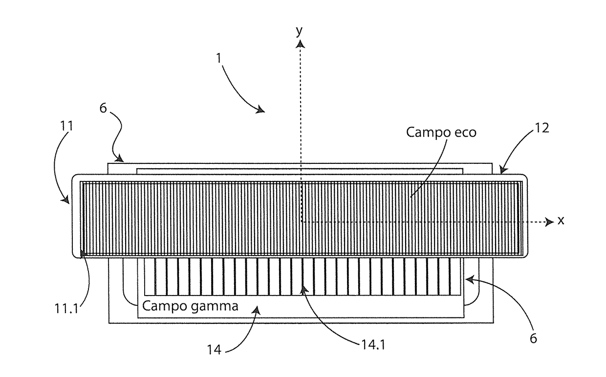
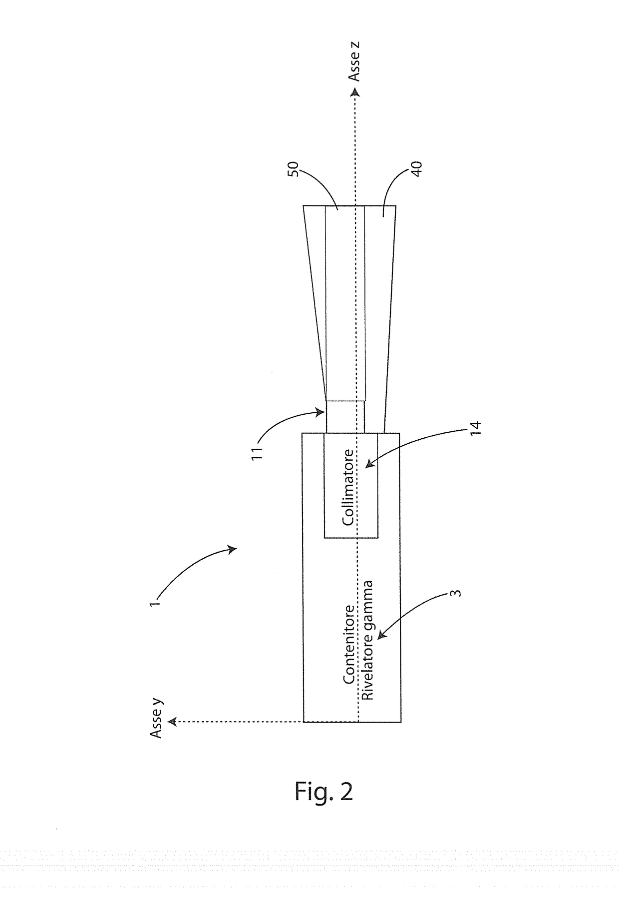
[0081]Referring to FIGS. 1 to 3, the echo-scintigraphic probe 1 according to the invention is schematically illustrated. The echo-scintigraphic probe is constituted by an echographic sensor and a scintigraphic sensor pointed in the same direction with the visual field of the second that contains the visual field of the first, which is mounted in such a way as to absorb a part of the gamma photons, producing a shadow on the plane of collection of the gamma photons of the scintigraphic sensor. More specifically, an echo-scintigraphic probe 1 is provided, which is placed in front of a collimator 14 which in turn is placed in line with a gamma camera 3. As can be seen from FIG. 2, the ultrasound probe 11 covers only a part of the collimator 14 and is slightly shifted from the axis of the collimator (“asymmetric” mounting). Despite this, the field of action 50 of the ultrasound probe and that 40 of the scintigraphic probe are in the Z direction, meaning that the scintigraphic probe sees ...


PUM


Abstract

An echo-scintigraphic probe for medical applications and the method of merging images. It is constituted by the union of an ultrasound probe suitably integrated, both in geometric terms, and in terms of image processing, with a scintigraphic probe or gamma camera (3). With a single application of said probe, one is able to provide a double image of the object under examination. The ultrasound probe is housed in the head, above the plane of the collimator and kept projecting to favor the direct contact with the body part of the patient to be examined. The collimator is able to obtain images of the biodistribution of a radiolabelled drug by radiation with frontal incidence, maintaining the characteristics of the ultrasound probe. The probe is applicable to both clinical diagnosis and intraoperative diagnosis of cancer with the use of radio tracers. A guided diagnostic method is disclosed that realizes a functional integration of a pair of ultrasound and scintigraphic images concurrently obtained by the echo-scintigraphic probe.

Description

FIELD OF THE INVENTION[0001]The present invention relates to an echo-scintigraphic probe for medical and related diagnostic method.[0002]More specifically, the probe according to the invention includes both an ultrasound probe and a scintigraphic probe, assembled in such a way that, in one pass on the area to investigate, it provides two images of the same area which will then be integrated by the method according to the invention, providing a guide to the investigation. It was devised to solve the current problems related to the complexity of the current large and expensive imaging systems in general and in particular for those techniques based on the use of a tomographic ring integrated with at least two detectors, such as SPECT CT, PET CT, CT SNMR and recently PET NMR.BACKGROUND[0003]In medicine, extensive use of instrumentation is made to obtain images in the diagnosis of diseases.[0004]In particular, both the ultrasound images and the scintigraphic one are used for the secondar...

Claims


Application Information

Patent Timeline
IPC IPC(8): A61B6/00G01T1/161G01T1/16A61B8/00
CPCA61B6/5247A61B6/4258G01T1/1603A61B8/4444G01T1/1612A61B8/4416A61B8/463
Inventor PANI, ROBERTOORSOLINI CENCELLI, VALENTINOFABBRI, ANDREA
Owner UNIV DEGLI STUDI DI ROMA LA SAPIENZA
Why Eureka
Try Eureka