
Downhole Tool Coupling and Method of its Use

Inactive Publication Date: 2017-03-23
REEVES WIRELINE TECH
View PDF1 Cites 0 Cited by
  • Summary
  • Abstract
  • Description
  • Claims
  • Application Information

AI Technical Summary

Benefits of technology

The invention is a downhole tool coupling comprising two parts that can be locked together using magnets, capacitors, or inductors. The parts can be made of strong materials that can withstand harsh downhole environments. The coupling is designed to be easily connected and disconnected, and to prevent the ingress of fluids or contaminants while still allowing for the transmission of data and power. The components are completely isolated from each other, which prevents corrosion or abrasion. The coupling is also designed to be long-lasting and can withstand impact damage during deployment and handling.

Problems solved by technology

This makes it hard to communicate with a logging tool that is conveyed a significant distance along the borehole.
An autonomous logging tool however is not normally capable of signalling correct deployment at its downhole location; nor is it usually capable of sending log data to a surface location in real-time; nor may it normally receive complex control commands from a surface location.
These mud pulses however amount to very narrow bandwidth, low bit-rate communications that are not at all suitable for conveying log data in real-time.
Moreover the mud pulses require energy to generate and can be ambiguous due to their propagation over many thousands of feet of the borehole depth.
Mud pulse signalling therefore is often of little help in the controlling of logging tools and the rapid acquisition of data.
As drilling a borehole takes significant time, typically days, slow data rates although a disadvantage are useable in this application.
However one difficulty associated with wireline logging tools is that it is not generally possible to maintain a connection during e.g. an LWD operation since the wireline presents an obstacle to jointing of the drill pipe at the surface.
Gathering data from the tool under such circumstances necessarily requires the movement of drill pipe.
The downhole environment is usually extremely harsh, partly because of significant fluid pressures that exist and also because various chemicals present in boreholes are not compatible with the use of electrical signals for data and power transmission.
This could be because the chemicals are for example chemically aggressive and thereby degrade connector terminals, or because they are electrically conducting or insulating in ways that can interfere with the performance of electrical and electronic equipment exposed to them.
The damaging physical conditions in a downhole location make it extremely hard to design a reliable, releasable connector that meets the multiple requirements set out above.
Many such connection designs cannot be “made” after being “broken” in a downhole situation as may occur when the wireline is pulled away from the toolstring.
Wet connectors however suffer from numerous problems one of which is that if any borehole fluid becomes interposed between the terminals respectively of the male and female elements, undesirable short circuits, open circuits and other anomalies, depending on the character of the borehole fluid, may arise.
Certain wet connector designs include features the aim of which is to minimise the chance of borehole fluid ingress in this way but these features often are not successful.
As a result for example the anti-ingress features may make it less likely on mating of the male and female connector elements that the terminals will contact one another in a satisfactory manner.
Moreover borehole fluids as indicated may be chemically aggressive, abrasive and / or under very high pressure.
These factors tend to make the anti-ingress features of the wet connectors fail prematurely.
Yet another problem associated with wet connectors is that they tend to occupy a large volume in the vicinity of the toolstring parts requiring connection.
This makes them unsuited for use in conjunction with mechanical latch arms of the kind that are often used for the temporary securing of parts of a toolstring, such as relatively uphole and downhole elements of a sonde assembly, together.

Method used


Image

  • Downhole Tool Coupling and Method of its Use
  • Downhole Tool Coupling and Method of its Use
  • Downhole Tool Coupling and Method of its Use

Examples


Embodiment Construction

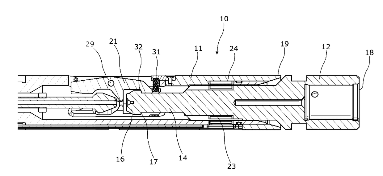
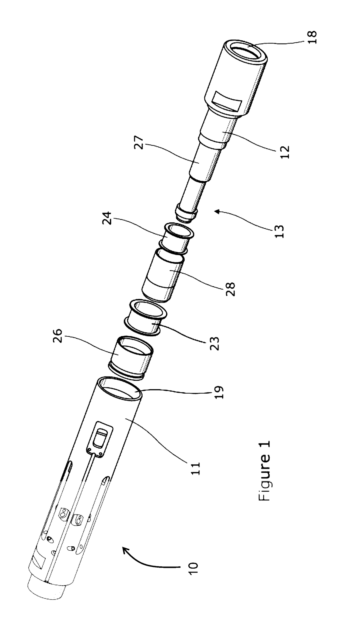
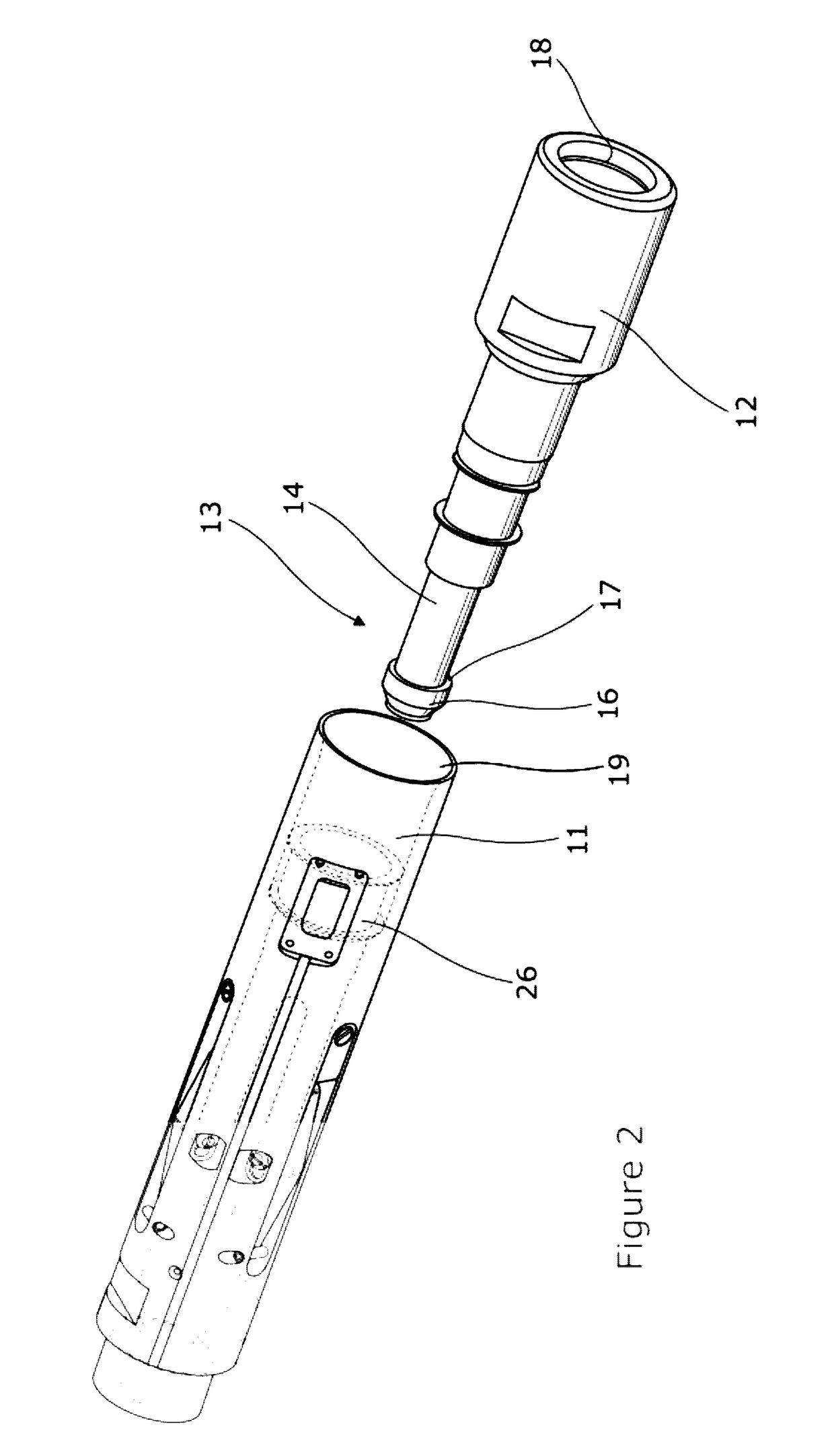
[0075]Referring to the drawings a downhole tool coupling 10 comprises two principal components in the form of first and second tool elements 11, 12 that are intended for selective coupling together to form a connected toolstring; and releasing, in a downhole environment such as a subterranean borehole. The nature of the tool coupling of the invention is to provide reliable communications and / or power connection between the components 11, 12.

[0076]As is almost inevitably the case in respect of toolstring elements in a downhole environment, one 11 of the tool elements is located relatively uphole of the other, 12, that therefore may be regarded as existing in a relatively more downhole position.

[0077]In the embodiment illustrated the relatively more uphole tool element 11 is constituted as a latching sub formed at the in use downhole end of an upper sonde section that may for example be a receiver of logging energy that has been passed through rock surrounding the borehole in which th...


PUM


Abstract

A downhole tool coupling (10) comprises first (11) and second (12) downhole tool elements that are securable one to the other in a releasably locking manner by moving the tool elements from a longitudinally relatively less proximate, especially overlapping position into longitudinally relatively more overlap with one another. The first downhole tool element (11) supports a first inductive, capacitative and / or magnetic energy coupler (23) and the second downhole tool element (12) supports a second inductive, capacitative and / or magnetic energy coupler (24). The first and second energy couplers (23, 24) are moveable from an energetically uncoupled position when the tool elements (11, 12) are in the longitudinally relatively less overlapping position to an energetically coupled position when the first and second downhole tool elements (11, 12) overlap relatively more.

Description

CROSS-REFERENCE TO RELATED APPLICATIONS[0001]This application is a continuation-in-part of U.S. application Ser. No. 13 / 905,257, filed 30 May 2013, which is incorporated herein by reference and which claims the benefit under 35 U.S.C. §119(a) to U.K. Appl. No. GB 1209805.9, filed 1 Jun. 2012.FIELD OF THE DISCLOSURE[0002]The invention relates to a downhole tool coupling, in particular of a kind that is suitable for coupling elements of logging toolstrings in downhole locations.BACKGROUND OF THE DISCLOSURE[0003]As is well known, prospecting for minerals of commercial or other value (including but not limited to hydrocarbons in liquid or gaseous form; water e.g. in aquifers; and various solids used e.g. as fuels, ores or in manufacturing) is economically an extremely important activity. For various reasons those wishing to extract such minerals from below the surface of the ground or the floor of an ocean need to acquire as much information as possible about both the potential commerci...

Claims


Application Information

Patent Timeline
IPC IPC(8): E21B17/02E21B47/12
CPCE21B47/12E21B17/028E21B17/023E21B17/0283
Inventor PIKE, JAMES ARTHUR
Owner REEVES WIRELINE TECH
Features
  • Generate Ideas
  • Intellectual Property
  • Life Sciences
  • Materials
  • Tech Scout
  • Unparalleled Data Quality
  • Higher Quality Content
  • 60% Fewer Hallucinations
Learn More