Catalyst layer for a fuel cell and method for the production thereof

a fuel cell and catalyst layer technology, applied in the direction of fuel cells, sustainable manufacturing/processing, climate sustainability, etc., can solve the problems of voltage drop, inapplicability to conventionally designed fuel cells, and complex methods, and achieve the effect of reducing production costs, handling and applying

Active Publication Date: 2017-03-23
AUDI AG
View PDF5 Cites 3 Cited by
  • Summary
  • Abstract
  • Description
  • Claims
  • Application Information

AI Technical Summary

Benefits of technology

[0031]The ink may be applied to the substrate with any suitable method, including both manual methods as well as machine methods, for example, brushing on by hand, coating with the notched bar, coating with a fluid-bearing nozzle, coating with a wirewound rod, coating with the aid of a doctor knife with a slot feed, coating with three rollers or peel-off transfer. In the case of peel-off transfer, the ink is first applied to a transfer substrate and dried and subsequently transferred as a transfer picture to the substrate. The coating may be accomplished in one application or in multiple work steps. After coating, the ink may be dried in an oven or the like in air at temperatures of greater than 80° C., typically greater than 110° C. and preferably greater than 140° C. The ink according to the present invention preferably does not self-ignite when it is fully dried under these conditions. An ink that does not self-ignite during drying is also generally safer to produce, handle and to apply.

Problems solved by technology

However, these methods are very complex and not applicable to conventionally designed fuel cells.
In addition, it has been found that an accumulation of water alone in the active area of a fuel cell caused a voltage drop during operation of the fuel cell.

Method used


Image

  • Catalyst layer for a fuel cell and method for the production thereof
  • Catalyst layer for a fuel cell and method for the production thereof
  • Catalyst layer for a fuel cell and method for the production thereof

Examples


Embodiment Construction

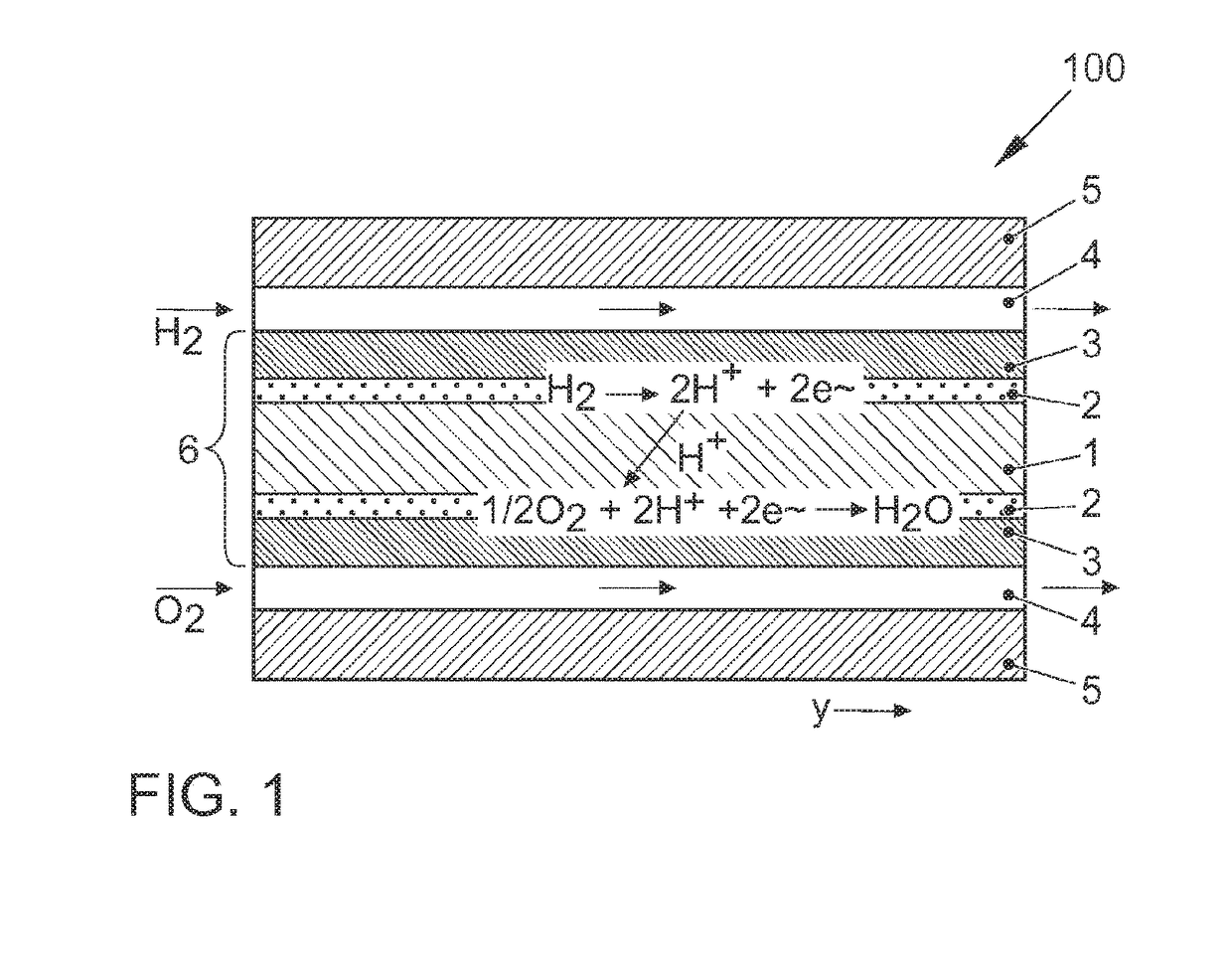
[0036]A schematic sectional view of an individual cell of a PEM fuel cell, identified in its entirety with reference numeral 100, is depicted in FIG. 1 for explaining the structure and its mode of operation.

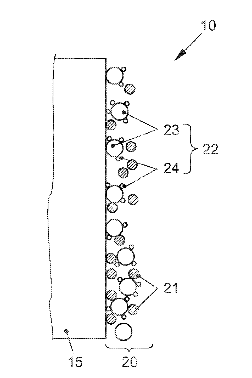
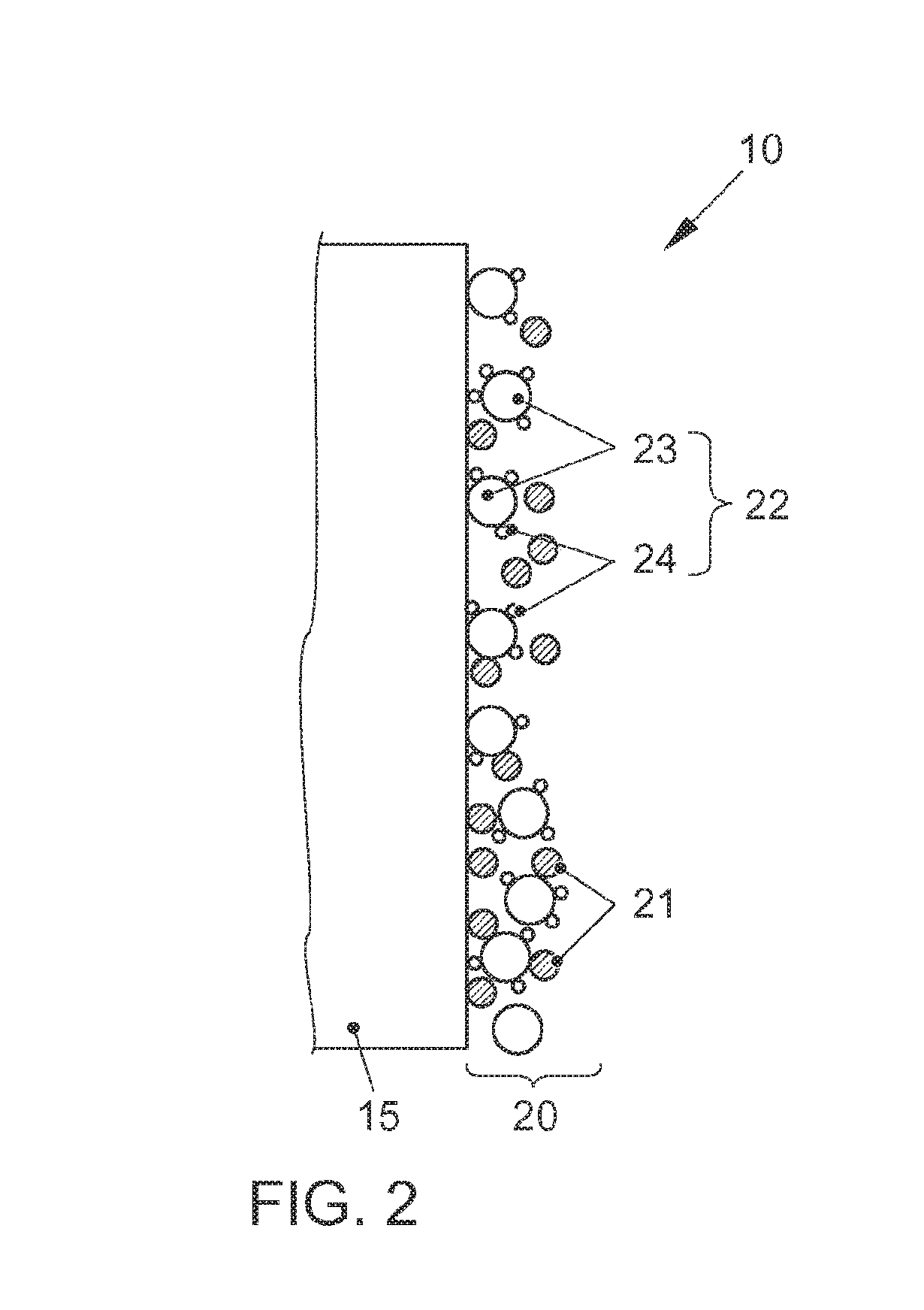
[0037]Fuel cell 100 includes as its core component a membrane electrode assembly 6, which has a polymer electrolyte membrane 1 as well as one electrode 2 each, namely, an anode and a cathode, attached on one or both flat sides of membrane 1. Polymer electrolyte membrane 1 is a cation-, in particular, proton (H+)-conducting membrane. Electrodes 2 include a catalytic material, which may be supported on an electrically conductive material, for example, a carbon-based material.

[0038]A gas diffusion layer 3 is attached to each electrode 2, which is essentially assigned the task of uniformly distributing the supplied process gases over the main surfaces of electrodes 2, and membrane 1.

[0039]A bipolar plate 5 is situated on the outside of each gas diffusion layer 3. Bipolar plates have ...


PUM

PropertyMeasurementUnit
pore diameteraaaaaaaaaa
sizeaaaaaaaaaa
temperaturesaaaaaaaaaa

Abstract

A catalyst layer (20) for a fuel cell and to a method suitable for producing the catalyst layer (20). The catalyst layer (20) includes a catalyst material (22) containing a catalytic material (24) and optionally porous carrier material (23) on which the catalytic material (24) is supported. The catalyst layer also includes mesoporous particles (21) made from hydrophobic material.

Description

[0001]The present invention relates to a catalyst layer for a fuel cell, including a catalyst material containing a catalytic material and, optionally, a porous carrier material, on which the catalyst material is supported, as well as a method for manufacturing the catalyst layer.BACKGROUND[0002]Fuel cells utilize the chemical reaction of a fuel with oxygen yielding water, in order to generate electrical energy. For this purpose, fuels cells contain as a core component the so-called membrane electrode unit (MEA for membrane electrode assembly), which is a combination of a proton-conducting membrane and one electrode each (anode and cathode) situated on either side on the membrane. In addition, gas diffusion layers (GDL) may also be situated on either side of the membrane electrode assembly on the sides of the electrodes facing away from the membrane. The fuel cell is generally formed by a plurality of MEAs arranged in a stack, whose electric power outputs are added up. During operat...

Claims


Application Information

Patent Timeline
Patent Type & Authority Applications(United States)
IPC IPC(8): H01M4/86H01M4/88
CPCH01M4/8663H01M4/8807H01M2008/1095H01M4/8828H01M4/881H01M8/1004H01M4/8605Y02P70/50Y02E60/50
Inventor BANHAM, DUSTINFRIESS, BROOKSYE, SIYU
Owner AUDI AG
Why Eureka
Try Eureka