Structural porous biomaterial and implant formed of same

a biomaterial and microstructure technology, applied in the field of prosthetic implants, can solve the problems of less capable of solving the conflicting nature of physiological phenomena occurring in implants, uneven cell distribution, and inability to provide the strength required for all applications, and achieve the effect of improving the mechanical properties of cells

Active Publication Date: 2017-04-06
MCGILL UNIV
View PDF10 Cites 49 Cited by
  • Summary
  • Abstract
  • Description
  • Claims
  • Application Information

AI Technical Summary

Benefits of technology

[0033]In accordance with a further aspect of the present invention, there is provided the implant and / or structural porous biomaterial as described above, wherein one or more joint between said struts of the cells have local reinforcement to improve the mechanical properties of the cells formed thereby, without materially affecting the pore size.

Problems solved by technology

These material characteristics, however, have been found to be less capable of solving the conflicting nature of the physiological phenomena occurring in an implant (Kuiper and Huiskes, 1992, Recent Advances in Computer Methods in Biomechanics & Biomedical Engineering, J. Middleton, G N Pande and K R Williams, 76-84; Kuiper and Huiskes, 1997, Transactions-American Society of Mechanical Engineers Journal of Biomechanical Engineering, 1919: 166-174).
Whereas the reduced stiffness of the foam decreases bone resorption, the uniform distribution of cells has the undesired effect of increasing the interface stresses.
Accordingly, while these known implants and porous biomaterials permit bone ingrowth, they may not always provide the strength required for all applications, particularly those where load-bearing bone replacement is required.
Additionally, the properties of these biomaterials, and thus the bone implants formed thereby, cannot typically be modified or selected based on the requirements of the given application and / or patient, and are thus difficult to design for the specific local bone tissue of a patient.

Method used


Image

  • Structural porous biomaterial and implant formed of same
  • Structural porous biomaterial and implant formed of same
  • Structural porous biomaterial and implant formed of same

Examples


experimental example

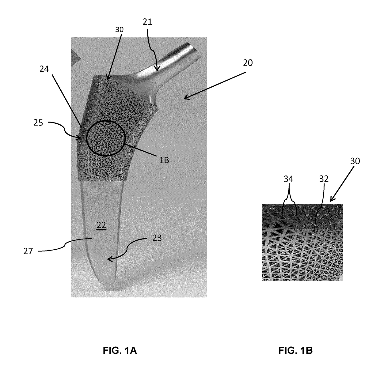
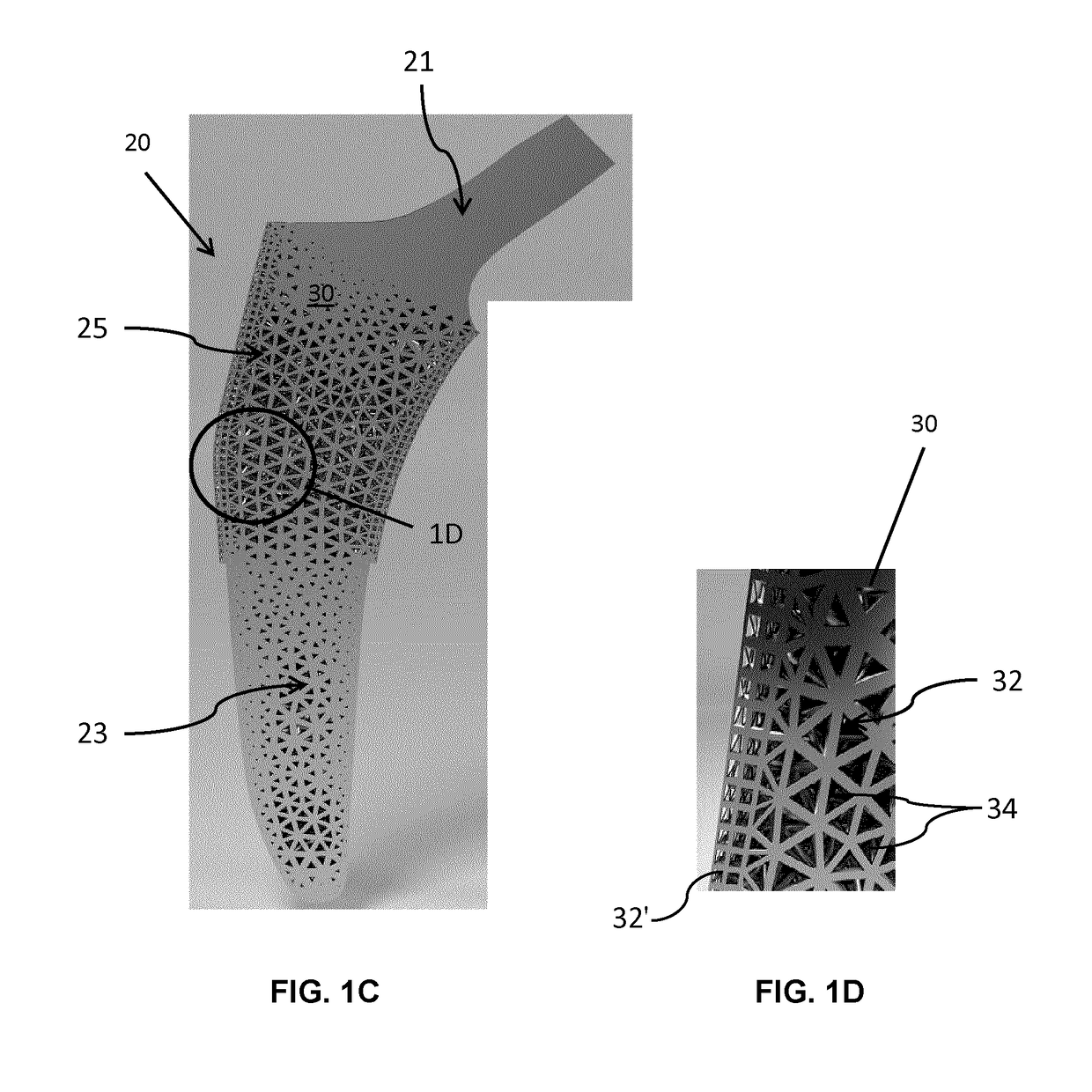
[0104]Referring now to FIGS. 3A and 3B, unit cells forming the fully tessellated lattices 132 and 332 described above, namely the octet truss cell 134 (FIG. 3B) the tetrahedron cell 334 (FIG. 3A) respectively, will now be described in further detail. Both of these cell topologies are high-strength, stretching dominated, topologies which were designed, fabricated and tested by the inventors in the manner described below.

[0105]Using Selective Laser Melting (SLM), two design points were fabricated within constraints for both tetrahedron 334 and octet truss 134 cells, in order to assess the bone ingrowth and apposition at four and eight week intervals in a canine model. Bone ingrowth was shown to occur with these two high strength lattice cell topologies. To further investigate the mechanical strength of these two cell topologies, the inventors manufactured eight design points with SLM, and the deviation was quantified between designed and manufactured morphological parameters using Mic...


PUM

PropertyMeasurementUnit
pore sizeaaaaaaaaaa
pore sizeaaaaaaaaaa
thicknessaaaaaaaaaa

Abstract

An implant comprising a porous microstructure is disclosed which has an external surface, where at least a region of the external surface is formed of the porous microstructure. The microstructure is defined by at least one lattice of cells. Each cell has a predetermined cell topology and a plurality of edges. One or more of the edges of each cell connect to an adjacent cell along a corresponding edge thereof. Collectively, the cells have a periodic or aperiodic arrangement within the at least one lattice.

Description

TECHNICAL FIELD[0001]The application relates generally to prosthetic implants, and, more particularly, to an implant with a porous microstructure for bone replacement.BACKGROUND[0002]Certain existing orthopedic and dental bone-replacement implants are formed of a material, or are surface treated with an external coating or material, which is intended to encourage bone ingrowth from the local bone tissue against or within which they are implanted. For example, implants used in total hip replacement formed of a microstructural material over a fully dense material have been attempted. Hip implants with porous tantalum have also been proposed in knee and hip replacement surgery. (Bobyn et al., 2004, The Journal of Bone and Joint Surgery, 86: 123).[0003]Open cell structures for bone implants formed of tantalum applied by chemical vapor deposition onto a carbon foam substrate are also known, as described for example in U.S. Pat. No. 5,282,861 by Kaplan, which provides bone implants so for...

Claims


Application Information

Patent Timeline
Patent Type & Authority Applications(United States)
IPC IPC(8): A61F2/30A61L27/56A61L27/36A61F2/36
CPCA61F2/30767A61F2/3662A61L27/56A61L27/365A61F2002/30275A61L2430/02A61F2002/3092A61F2/367A61F2/3672A61F2/3676A61F2002/3028A61F2/36Y02P10/25
Inventor PASINI, DAMIANOTANZER, MICHAELARABNEJAD, SAJAD KHANOKIJOHNSTON, BURNETT
Owner MCGILL UNIV
Why Eureka
Try Eureka