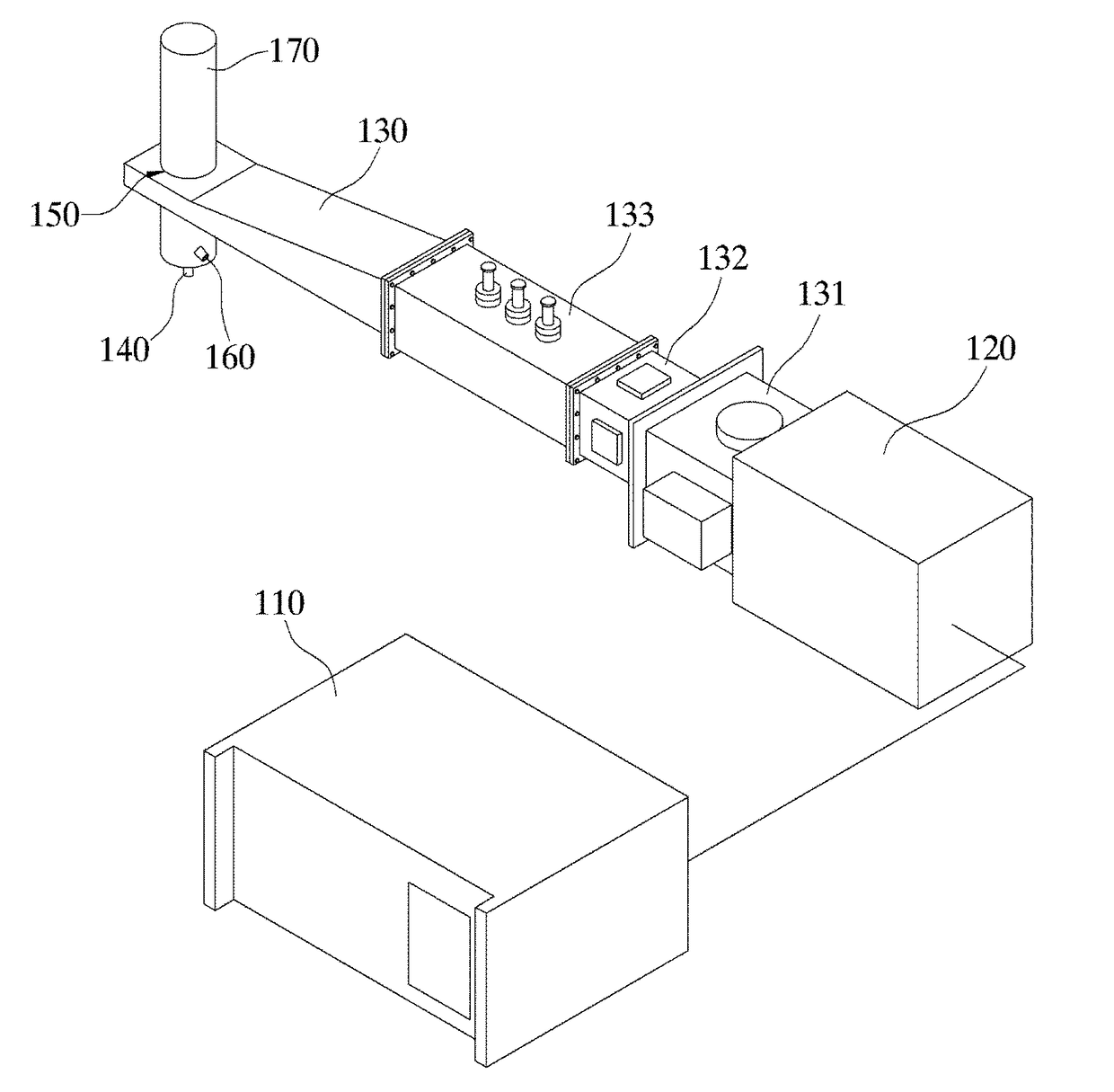
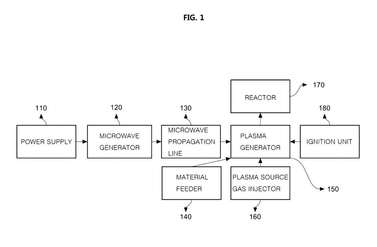
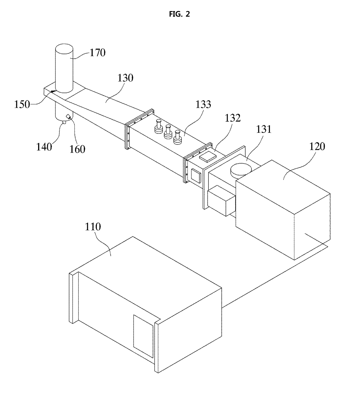
Microwave plasma torch

a plasma torch and microwave technology, applied in the field of microwave plasma torch, can solve the problems of difficult injection of to-be-treated materials into the torch, and the application of plasma torch has not required a massive plasma treatmen

Active Publication Date: 2017-04-06
KOREA INST OF FUSION ENERGY
View PDF2 Cites 10 Cited by
  • Summary
  • Abstract
  • Description
  • Claims
  • Application Information

AI Technical Summary

Benefits of technology

[0013]The present disclosure is to provide a massive plasma torch by removing the shortcomings of the conventional device that a specific frequency limits a plasma volume.
[0014]Further, the present disclosure is to provide a massive plasma torch which makes it easy to inject the to-be-treated material into the torch, wherein the plasma torch has a temperature has a lower point in a central portion of the discharge tube, and a higher point in an outer circumference of the discharge tube.
[0030]Further, in accordance with the present disclosure, the microwave plasma torch may have various applications including plasma gasification, waste gas purification or modification, nano-material synthesis, NOx production, etc. Moreover, in accordance with the present disclosure, the microwave plasma torch may enable the massive treatment.

Problems solved by technology

The plasma torch generated from the conventional device has shortcomings that a specific frequency limits a plasma volume, and, thus, due to the limited plasma volume, the plasma torch has not applications requiring a massive plasma treatment.
This may lead to a pressure difference between the central portion and outer circumference of the discharge tube, which makes it difficult to inject a to-be-treated material into the torch.

Method used


Image

  • Microwave plasma torch
  • Microwave plasma torch
  • Microwave plasma torch

Examples


Embodiment Construction

[0047]Examples of various embodiments are illustrated and described further below. It will be understood that the description herein is not intended to limit the claims to the specific embodiments described. On the contrary, it is intended to cover alternatives, modifications, and equivalents as may be included within the spirit and scope of the present disclosure as defined by the appended claims.

[0048]It will be understood that, although the terms “first”, “second”, “third”, and so on may be used herein to describe various elements, components, regions, layers and / or sections, these elements, components, regions, layers and / or sections should not be limited by these terms. These terms are used to distinguish one element, component, region, layer or section from another element, component, region, layer or section. Thus, a first element, component, region, layer or section described below could be termed a second element, component, region, layer or section, without departing from ...


PUM


Abstract

There is provided a microwave plasma torch system comprising: a plasma generator; a microwave generator; and at least one plasma source gas injector, wherein the microwave generator includes a waveguide, wherein the plasma generator includes a discharge tube, wherein the discharge tube passes through a waveguide in a perpendicular to the waveguide, wherein the waveguide has a width na, where n is an integer equal to or larger than 2, wherein a is defined as a width of a waveguide having a dominant mode for propagating a microwave, wherein the discharge tube is positioned relative to the waveguide such that a diameter center of the tube encounters a longitudinal null line of an electric field distribution, wherein the discharge tube is further positioned relative to the waveguide such that a diameter center of the tube encounters a transverse null line of an electric field distribution, wherein the transverse null line is perpendicular to the longitudinal null line.

Description

CROSS-REFERENCE TO RELATED APPLICATION[0001]This application claims the benefit of Korea patent application No. 10-2014-0031927, filed on Mar. 19, 2014, the entire content of which is incorporated herein by reference for all purposes as if fully set forth herein.BACKGROUND[0002]Field of the Present Disclosure[0003]The present disclosure relates to a microwave plasma torch, and, more particularly, to a massive microwave plasma torch.[0004]Discussion of Related Art[0005]A microwave plasma torch has been widely employed. Korean Patent Number 10-1166444 discloses a plasma source gas torch using a microwave, and applications thereof, to heat a plasma source gas using a microwave to generate a pure plasma torch, and feed a hydrocarbon compound in a gas, liquid, or solid state to the generated plasma source gas plasma to produce a synthesized gas source. Further, Korean Patent Number 10-0375423 discloses a soot and smoke removal.[0006]Such devices using the plasma torch have had various ap...

Claims


Application Information

Patent Timeline
Patent Type & Authority Applications(United States)
IPC IPC(8): B01J19/08H05H1/30
CPCB01J19/088B01J2219/0805B01J2219/0894H05H1/30
Inventor HONG, YONG-CHEOL
Owner KOREA INST OF FUSION ENERGY
Why Eureka
Try Eureka