Vehicle climate control system

a technology for climate control systems and vehicles, applied in vehicle components, vehicle heating/cooling devices, transportation and packaging, etc., can solve the problems of engine cooling fan operation contributing to inefficient air conditioning operation, significant reduction of overall compressor efficiency, and increased fuel consumption. the effect of basic fuel consumption

Active Publication Date: 2017-04-06
INT TRUCK INTPROP LLC
View PDF4 Cites 30 Cited by
  • Summary
  • Abstract
  • Description
  • Claims
  • Application Information

AI Technical Summary

Benefits of technology

[0014]This disclosure introduces a climate control system for the interior, sometimes referred to as the cabin or occupant compartment, of an automotive vehicle in which both interior temperature and interior relative humidity are controlled by a system controller to maintain temperature and relative humidity of interior air within a comfort zone. Maintaining control within a comfort zone enables significantly improved efficiency at the system component level, resulting in reduction of basic fuel consumption as needed for vehicle HVAC (heating, ventilating, air conditioning) systems as well as enabling vehicle interior comfort without operation of the vehicle engine (idle reduction). Control is provided by at least one algorithm, look-up table, or the like which define correlations of air temperature and relative humidity which are considered to provide a generally acceptable comfort zone for most people. The correlations are empirically derived and / or mathematically calculated.

Problems solved by technology

However, that significantly reduces overall compressor efficiency because when the vehicle is being propelled by the engine, the engine is operating the compressor at speeds which are significantly greater than speeds which provide best compressor operating efficiency.
At low vehicle speeds, cooling fan operation may create additional noise, as well as drawing dust and dirt through the condenser.
Engine cooling fan operation contributes to inefficient air conditioning operation because typical fan operation uses significantly more power (perhaps as much as fifty or more horsepower) than that required to draw air through the condenser (typically less than one horsepower).
In summary, the typical vehicle air conditioning system loses efficiency due to high compressor speeds, to the use of the engine coolant fan for condenser air flow, to the mixing of heated air from the heater core with cold air delivered from the evaporator, and to operation of the evaporator in the 35°-45° F. temperature range.

Method used


Image

  • Vehicle climate control system
  • Vehicle climate control system
  • Vehicle climate control system

Examples


example 1

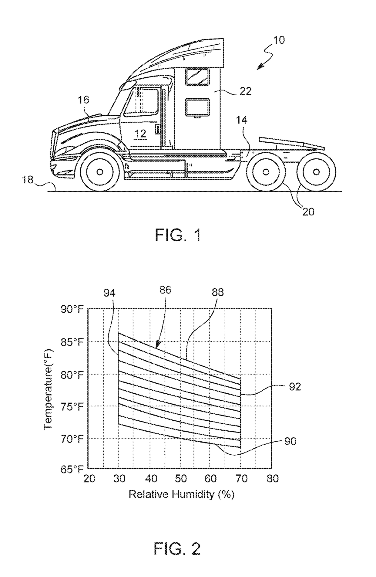
r Initially has 90° F. Temperature and 90% Relative Humidity

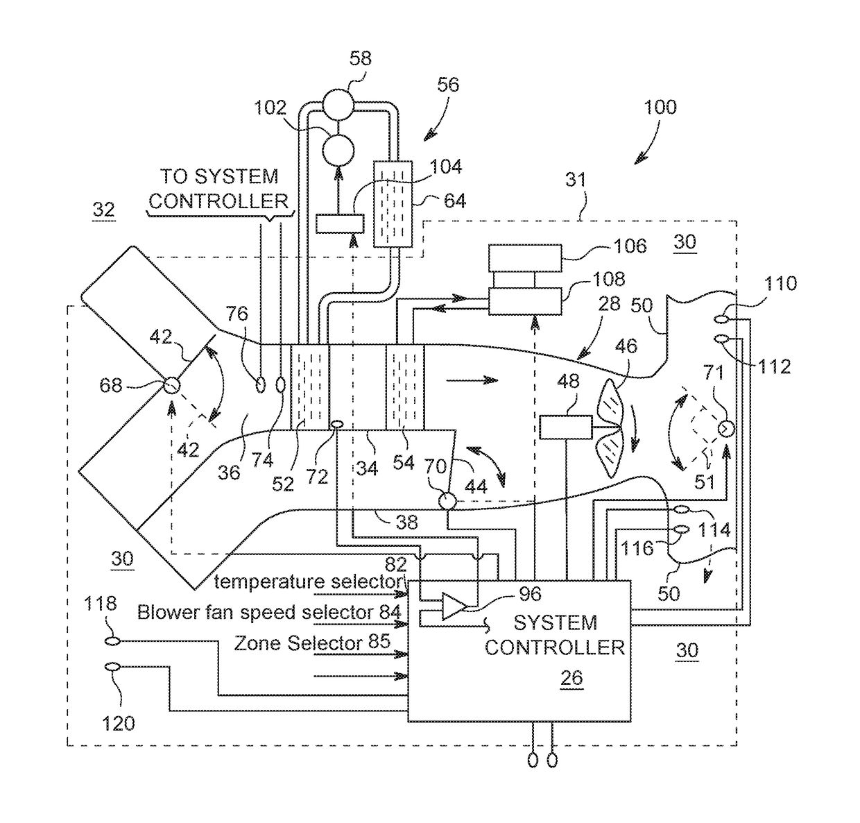
[0059]When temperature / relative humidity are beyond either or both boundaries 88, 92 of comfort zone 86, compressor 58 operates to remove thermal energy from air moving across heat exchange surfaces of cooler 52 and thereby decrease both temperature and relative humidity of inside air 30. Inside air is conditioned most quickly if both damper 44 is closed to block flow through secondary airway 38 and damper 42 is positioned to allow inside air 30 to enter airway 34 for recirculation while blocking outside air 32 from entering. Temperature of heat exchange surfaces of cooler 52 is controlled to be slightly less than the dew point temperature of inside air 30 being recirculated through primary airway 34. The magnitude of the difference between temperature of heat exchange surfaces of cooler 52 and dew point temperature of inside air is controlled to be not greater than a defined temperature difference as the temperature of ins...

example 2

r Initially has 85° F. Temperature and 25% Relative Humidity

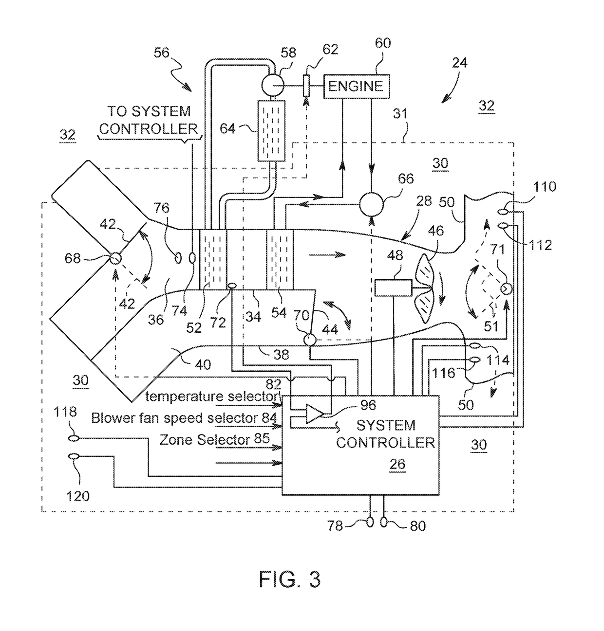
[0069]This condition often exists in portions of Arizona. The ratio of recirculated inside air 30 to fresh outside air 32 may be made smaller than in Example 1) because a smaller ratio may not have a significant effect on increasing relative humidity of inside air 30, and indeed may be desirable for better freshening (increased oxygen content) of inside air 30 breathed by the driver (and any other occupants) while maintaining occupant compartment temperature and relative humidity within comfort zone 86. Because cooler 52 is both removing moisture from, and also reducing the temperature of, air passing through it, the relative humidity of inside air 30 is also being reduced, and because less moisture needs to be removed from low relative humidity air, a temperature of reduced relative humidity air which needs to be reached in order for inside air 30 to enter comfort zone 86 can be higher than if outside air 32 had higher rel...


PUM


Abstract

A vehicle climate control system has a control strategy which controls temperature of an evaporator in a refrigeration circuit to achieve a target temperature / relative humidity within a comfort zone which is defined by upper and lower temperature boundaries and upper and lower relative humidity boundaries. Several system embodiments are disclosed, including an all-electric system. All systems operate with improved efficiency.

Description

PRIORITY CLAIM[0001]This application claims priority of Provisional Patent Application No. 62 / 216,210 filed on Sep. 9, 2015, the entire content of which is incorporated herein by reference.FIELD[0002]This disclosure relates to automotive vehicles, meaning any self-propelled on-road or off-road vehicle, such as a commercial truck for example, and in particular it relates to a climate control system for an automotive vehicle.BACKGROUND[0003]The climate control system for the interior of many currently manufactured automotive vehicles comprises both a heater and an air conditioner. In an automotive vehicle having such a climate control system, both heater and air conditioner rely on a prime mover, such as an internal combustion engine, which propels the vehicle in order to provide heating and cooling of the vehicle's interior.[0004]In an automotive vehicle which is propelled by an internal combustion engine, heating of the interior is provided by heat from engine coolant flowing throug...

Claims


Application Information

Patent Timeline
Patent Type & Authority Applications(United States)
IPC IPC(8): B60H1/32B60W30/14B60H1/22B60H1/00B60H3/02
CPCB60H1/3208B60H1/00807B60H3/024B60H1/00785B60W30/143B60H1/00842B60H1/3222B60H1/2215B60H1/00064B60H1/3207B60H2001/3245B60H2001/3283
Inventor LARSON, GERALD L.OPPERMAN, DEAN A.
Owner INT TRUCK INTPROP LLC
Why Eureka
Try Eureka