
Sealing fin armoring and method for the production thereof

a technology of sealing fins and armoring, which is applied in the direction of superimposed coating process, liquid fuel engines, machines/engines, etc., can solve the problems of difficult methods, insufficient wear resistance of the layer, and inability to achieve the coating of outward protruding sealing fins on the blade tips, etc., to achieve good oxidation resistance

Inactive Publication Date: 2017-04-06
MTU AERO ENGINES GMBH
View PDF13 Cites 3 Cited by
  • Summary
  • Abstract
  • Description
  • Claims
  • Application Information

AI Technical Summary

Benefits of technology

The invention proposes to apply a coating onto sealing fins using a slurry instead of spray coating. The slurry coating includes an oxidation-resistant MCrAlY layer that can be enriched with aluminum to ensure good oxidation resistance. Alternatively, a hard material layer can be deposited on the MCrAlY layer with aluminum enrichment existing in the edge region for even better performance. The combination of these coatings results in an abrasive coating with great oxidation resistance.

Problems solved by technology

Although good results in terms of the wear resistance have already been achieved, one problem is that such rotor blades need to be operated at higher operating temperatures in order to increase the efficiency, so that greater oxidation resistance is necessary.
Although it is known from EP 2 796 588 A1, the entire disclosure of which is incorporated by reference herein, to provide high-temperature protection coatings of an MCrAlY alloy for rotor blades, where M may be formed by iron, cobalt or nickel or combinations thereof, such layers nevertheless do not have a sufficient wear resistance.
Such methods, however, are difficult to carry out for the coating of outwardly protruding sealing fins on blade tips.

Method used


Image

  • Sealing fin armoring and method for the production thereof
  • Sealing fin armoring and method for the production thereof
  • Sealing fin armoring and method for the production thereof

Examples


Embodiment Construction

[0036]The particulars shown herein are by way of example and for purposes of illustrative discussion of the embodiments of the present invention only and are presented in the cause of providing what is believed to be the most useful and readily understood description of the principles and conceptual aspects of the present invention. In this regard, no attempt is made to show details of the present invention in more detail than is necessary for the fundamental understanding of the present invention, the description in combination with the drawings making apparent to those of skill in the art how the several forms of the present invention may be embodied in practice.

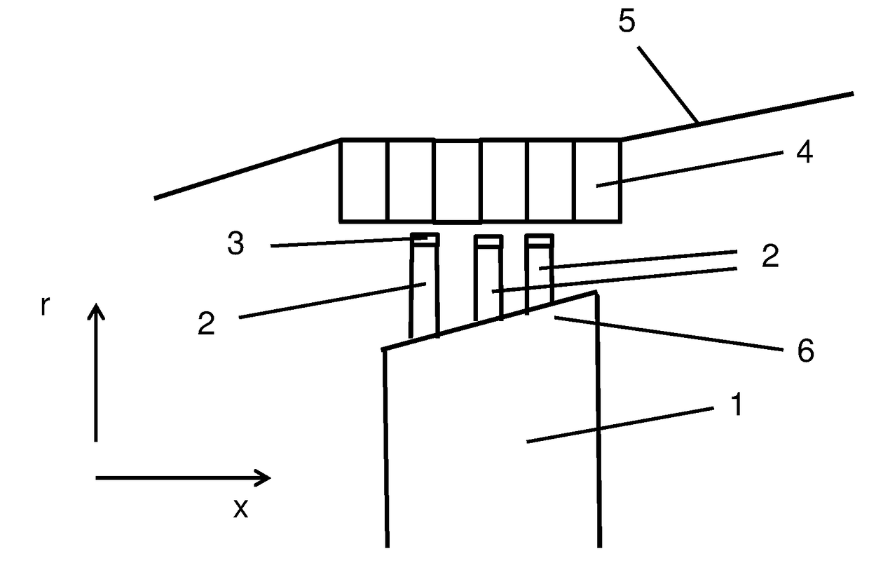
[0037]FIG. 1 shows a detail of a turbomachine in a longitudinal section along the rotation axis of the turbomachine. In the detail shown, a rotor blade 1 can be seen which extends both in the axial x direction along the rotation axis of the turbomachine and in the radial direction r, the axial direction x and the radial di...


PUM

PropertyMeasurementUnit
Temperatureaaaaaaaaaa

Abstract

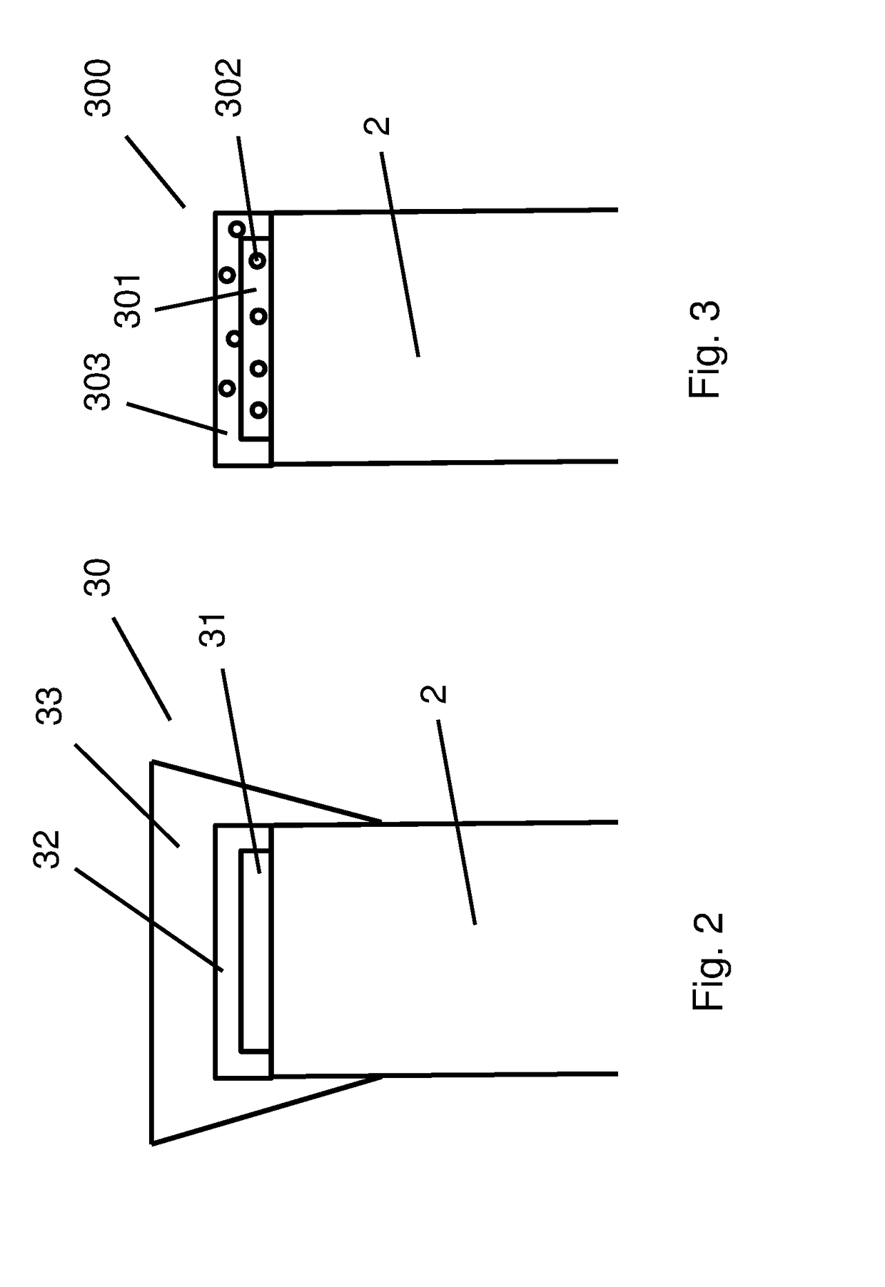
A method for coating a sealing fin (2) on a component of a turbomachine, in particular on a blade tip (6) of a blade (1) of a turbomachine, with armoring (3, 30,300), and to a corresponding component, in which method a blade (1) having at least one sealing fin (2) and a slurry which comprises particles of MCrAlY or particles for forming an MCrAlY layer (31), where M is nickel and / or cobalt, are provided, the slurry is applied onto the sealing fin and dried, and the sealing fin with the applied slurry is subjected to an aluminizing process so that the MCrAlY layer comprises an Al-rich sublayer (32).

Description

CROSS-REFERENCE TO RELATED APPLICATIONS[0001]The present application claims priority under 35 U.S.C. §119 of German Patent Application No. 102015213555.1, filed Jul. 20, 2015, the entire disclosure of which is expressly incorporated by reference herein.BACKGROUND OF THE INVENTION[0002]1. Field of the Invention[0003]The present invention relates to a method for coating at least one sealing fin of a component of a turbomachine, and in particular of a blade tip of a blade of a turbomachine, with armoring. The present invention furthermore relates to a component, and in particular a blade of a turbomachine, having at least one, and preferably a plurality of sealing fins on the blade tip, comprising armoring on the sealing fin or fins, the armoring comprising an MCrAlY layer, where M is nickel and / or cobalt.[0004]2. Discussion of Background Information[0005]In turbomachines, such as static gas turbines or aircraft engines, fluid such as air or combustion gases flows through a flow channe...

Claims


Application Information

Patent Timeline
IPC IPC(8): F01D11/08C23C4/134C23C24/04F04D29/38F01D5/14F04D29/08F04D29/32C23C4/129C23C4/131
CPCF01D11/08F05D2300/2263C23C4/134C23C24/04C23C4/131F01D5/147F04D29/083F04D29/324F04D29/388F05D2220/323F05D2230/90F05D2240/307F05D2300/177F05D2230/312F05D2230/311F05D2300/2112F05D2300/2118F05D2300/2282F05D2300/2262C23C4/129C23C4/02C23C10/08C23C24/085C23C28/324C23C28/345C23C28/3455C23C4/11F01D5/286F01D11/122F01D11/125
Inventor WERNER, ANDREPUSCH, MANUELUTZ, PHILIPPWALTER, HEINRICH
Owner MTU AERO ENGINES GMBH
Learn More