Organic light-emitting display and method for driving the same

Active Publication Date: 2017-04-06
LG DISPLAY CO LTD
View PDF4 Cites 25 Cited by
  • Summary
  • Abstract
  • Description
  • Claims
  • Application Information

AI Technical Summary

Benefits of technology

[0013]The present invention provides an organic light-emitting display dev

Problems solved by technology

However, electrical characteristics of driving TFTs of pixels are not uniform due to processing conditions, driving environment and the like.
For internal compensation, current flowing through OLED needs to be determined irrespective of a threshold voltage of a corresponding driving TFT and thus a pixel circuit configuration becom

Method used


Image

  • Organic light-emitting display and method for driving the same
  • Organic light-emitting display and method for driving the same
  • Organic light-emitting display and method for driving the same

Examples


Embodiment Construction

[0036]Preferred embodiments of the present invention will be described in detail with reference to the attached drawings. The same reference numbers will be used throughout this specification to refer to the same or like parts. In the following description of the present invention, a detailed description of known functions and configurations incorporated herein will be omitted when it may obscure the subject matter of the present invention.

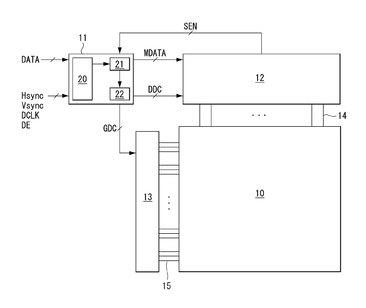
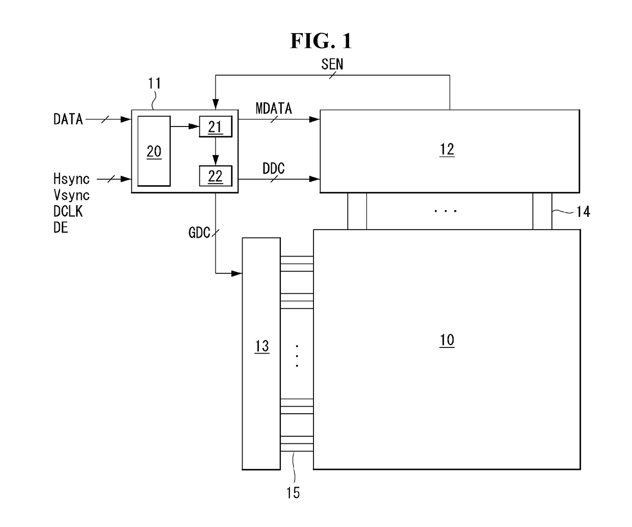
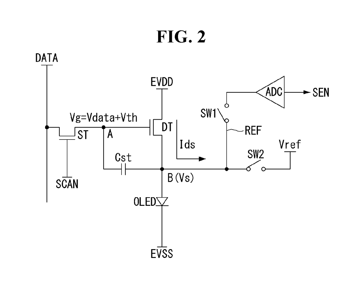
[0037]FIG. 1 is a block diagram of an organic light-emitting display device according to an embodiment of the present invention, FIG. 2 is an equivalent circuit diagram of a pixel shown in FIG. 1 and FIG. 3 is a waveform diagram showing a method for sensing a threshold voltage of a driving TFT shown in FIG. 2.

[0038]Referring to FIGS. 1 and 2, the organic light-emitting display device according to an embodiment of the present invention includes a display panel 10, a data driver 12, a gate driver 13 and a timing controller 11.

[0039]The display panel...


PUM


Abstract

An organic light-emitting display device and a method for driving the same are provided. The organic light-emitting display device analyzes input image data in unit of a window mask to detect a halftone data block, adjusts a voltage corresponding to grayscale 0 of center data disposed at the center of the halftone data block to a voltage higher than 0V, and adjusts the voltage corresponding to grayscale 0 in a data block other than the halftone data block to 0V, such that a data voltage swing width at low grayscales can be reduced so as to prevent voltage drop in pixels, thereby improving picture quality.

Description

[0001]This application claims priority from the benefit under 35 U.S.C. §119(a) of Korean Patent Application No. 10-2015-0139384 filed on Oct. 2, 2015, entire contents of which are incorporated herein by reference for all purposes as if fully set forth herein.BACKGROUND OF THE INVENTION[0002]Field of the Invention[0003]The present invention relates to an organic light-emitting display device for improving expression of low grayscales.[0004]Discussion of the Related Art[0005]Active matrix type organic light-emitting display devices include an organic light-emitting diode (referred to as “OLED” hereinafter) and have advantages of high response speed, high emission efficiency, high luminance and wide viewing angle. The OLED includes an organic compound layer formed between an anode and a cathode. The organic compound layer is composed of a hole injection layer (HIL), a hole transport layer (HTL), an emission layer (EML), an electron transport layer (ETL) and an electron injection layer...

Claims


Application Information

Patent Timeline
IPC IPC(8): G09G3/20G09G3/3233G09G3/3258G09G3/3275
CPCG09G3/2051G09G3/3275G09G3/3233G09G3/3258G09G2300/0819G09G2320/0238G09G2320/0276G09G2310/027G09G2310/0286G09G2320/0233G09G2310/08
Inventor JEONG, JAEHYEONGKIM, SEONGGYUN
Owner LG DISPLAY CO LTD
Why Eureka
Try Eureka