
Deployable aerodynamic bed cover system

a technology of aerodynamic bed cover and actuator, which is applied in the direction of vehicle body streamlining, roof, load-carrying vehicle superstructure, etc., can solve the problems of not meeting requirements, typical systems such as fixed panels, or motorized deployable panels, and not having a proper sealed and clutchable actuator with communication capability, so as to improve the clearance of the pickup cargo bed, improve the aerodynamics, and improve the effect of airflow

Active Publication Date: 2017-04-13
MAGNA EXTERIORS INC
View PDF42 Cites 17 Cited by
  • Summary
  • Abstract
  • Description
  • Claims
  • Application Information

AI Technical Summary

Benefits of technology

The present invention is a bed cover assembly for vehicles that has a deployable panel to improve aerodynamics. The panel moves between a stowed position and a deployed position driven by an actuator, which is sealed and has communication capability with the vehicle. The panel improves airflow at predetermined vehicle speeds and is only utilized when necessary. When the panel is in its retracted position, it does not interfere with bed access or cargo bed clearance. The bed cover system is a fully deployable, detects objects, and is flush when stowed. It reduces vehicle drag, improves fuel economy, and prevents damage to the bed from sliding objects.

Problems solved by technology

However, there is a considerable loss of aerodynamic efficiency in vehicles, in particular, pickup trucks and other vehicles having a storage bed, due to the airflow into the bed and over the tailgate.
Typical systems, such as fixed panels, or motorized deployable panels, do not meet requirements.
Known systems do not have a proper sealed and clutchable actuator with communication capability and life cycle durability, object detection, are not transparent to the vehicle when the tailgate is down, and are not durable and aerodynamically effective.
Conventional systems also have the potential to break or be damaged due to sliding objects in the pickup cargo bed.
Typical systems also do not have the ability to detect objects in the event there is cargo / objects in the way during deployment.

Method used


Image

  • Deployable aerodynamic bed cover system
  • Deployable aerodynamic bed cover system
  • Deployable aerodynamic bed cover system

Examples


first embodiment

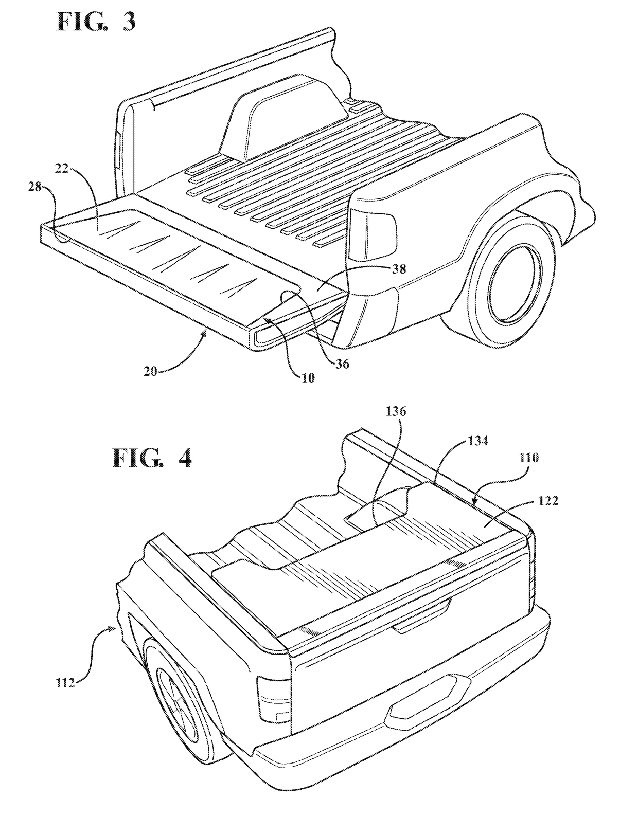
[0054]Referring to FIG. 4 generally, in accordance with another embodiment of the present invention, an active bed cover assembly generally shown at 110 for a vehicle 112 is identical to the first embodiment except that the deployable panel 122 as a different profile. The sides 134 are substantially straight and a cutout 136 is located along the leading edge of the panel 22 away from the proximal end forming a central cutout 136 with side wings or side extensions.

[0055]Referring to FIGS. 5-6 generally, in accordance with another embodiment of the present invention, an active bed cover assembly generally shown at 210 for a vehicle 212 is identical to the first embodiment except that the deployable panel 222 as a different profile in that the sides are straight and the distal end of the panel 222 extends substantially from one side wall 16 to the other 18.

[0056]The deployable panel 22, 122, 222 is made of a composite plastic in these particular embodiments. However, depending on the p...

fifth embodiment

[0059]Referring to FIGS. 10A-10B generally, in accordance with the present invention, there is provided an active bed cover assembly generally shown at 610 for a vehicle 612 movable between the deployed position (See FIG. 10A) and the stowed position. The deployable panel 622 and a track arrangement 642 embedded in the depression 636 formed in tailgate 620 and toward the upward inner edge of the side walls 616, 618 forms a garage door style panel system. A first set of rollers or the like are connected toward the first end of the panel 622 to follow the track (slide or roll) in an upward / downward direction (FIG. 10B) when the panel is driven by the actuator. A second set of rollers or the like are connected toward the second end of the panel 622 to follow the track (slide or roll) in an outward / inward direction (FIG. 10B) when the panel is driven by the actuator. FIG. 10B illustrates stages of deployment of the rollable panel from a stowed position to the deployed position and back....

ninth embodiment

[0064]Referring to FIGS. 14A-14D generally, in accordance with the present invention, there is provided an active bed cover assembly generally shown at 910 for a vehicle 912. A plurality of panels form an integrated stacking panel indicated generally at 922. At least three panels are shown, including a first panel 948 pivotably connected to the tailgate, a second panel 950 operably slidably connected to the first panel 948, and a third panel 958 which is operably slidably connected to the second panel 950. When in the stowed position (FIG. 14B) the integrated stacking panel 922 are folded or stacked up to one another and are embedded within the depression 936 of the tailgate such that the third panel 958 is flush with the tailgate.

[0065]Each panel 948, 950, 958 has a first end and a second end. The proximal end 954 of the first panel 948 is pivotally connected to the tailgate 920 toward the upper outer edge of a depression 936 formed in the tailgate. Preferably, the sides of the fir...


PUM


Abstract

An active bed cover system having at least one deployable panel and at least one actuator. The deployable panel extends and retracts based on vehicle requirements and provides reduction in vehicle drag, thereby reducing emissions and improving fuel economy. Additionally, it allows for the system to retract within the tailgate and / or cargo bed liner allowing for access to the bed and improved usability and aesthetics. The active bed cover provides a fully deployable system with object detection, declutching of the actuator to help prevent damage, and communication with the vehicle to determine proper deployment and function.

Description

CROSS-REFERENCE TO RELATED APPLICATIONS[0001]This application is a PCT International Application and claims benefit of U.S. Provisional Patent Application No. 61 / 968,438 filed Mar. 21, 2014. The disclosure of the above application is incorporated herein by reference.FIELD OF THE INVENTION[0002]The present invention relates to an active bed cover assembly integrated into a tailgate system and / or cargo bed area for automotive applications.BACKGROUND OF THE INVENTION[0003]There has been increasing desire to manufacture vehicles that meet or exceed environmental improvement requirements. However, there is a considerable loss of aerodynamic efficiency in vehicles, in particular, pickup trucks and other vehicles having a storage bed, due to the airflow into the bed and over the tailgate.[0004]Therefore, having parts with improved aerodynamics has become a well-received option typically effective toward helping to advance standards such as mileage requirements. There are also several other...

Claims


Application Information

Patent Timeline
Patent Type & Authority Applications(United States)
IPC IPC(8): B62D35/00B62D33/03B60J7/057B60J7/04B60J7/14B62D33/027B60J7/16
CPCB62D35/007B62D33/0273B62D33/03B60J7/0573B60J7/041B60J7/141B60J7/1621B62D35/001
Inventor POVINELLI, ANTHONY J.MATTHEWS, MARTIN R.
Owner MAGNA EXTERIORS INC
Features
  • Generate Ideas
  • Intellectual Property
  • Life Sciences
  • Materials
  • Tech Scout
  • Unparalleled Data Quality
  • Higher Quality Content
  • 60% Fewer Hallucinations
Learn More