
Module test socket for over the air testing of radio frequency integrated circuits

Active Publication Date: 2017-04-13
KEYSSA +1
View PDF0 Cites 39 Cited by
  • Summary
  • Abstract
  • Description
  • Claims
  • Application Information

AI Technical Summary

Benefits of technology

This patent describes a test system for capturing low energy electromagnetic emissions from high-frequency integrated circuits. The system includes a test socket assembly that directs the electromagnetic radiation from the circuit into a waveguide. The test socket is designed to optimize the coupling of the electromagnetic energy into the waveguide and reduces unwanted signals. The system can also have multiple waveguides for testing multiple circuits simultaneously or in parallel. The technical effects of this patent are improved testing of high-frequency integrated circuits and the ability to test multiple circuits at the same time.

Problems solved by technology

Using dedicated ports, however, increases design complexity and consumes valuable chip area that could be used for additional functionality.
However, the test coverage of KGD testing is limited to pass / fail testing.
The lack of parametric testing limits both developmental stage testing and product testing.
Horn antenna based test fixtures suffer from drawbacks related to their large size relative to the typical size of an RF IC DUT.
Horn antennas create physical limitations on how closely horn antennas may be placed relative to the DUTs and the minimum distance required between adjacent DUTs.
Horn antennas are large and use of them physically limits the distance between the antenna and DUT.
This necessarily results in bulky test fixtures.
Additionally, the distance between horn antennas and DUTs may inhibit the horn antennas' ability to capture electromagnetic signals transmitted by low energy DUTs.
This is undesirable because radiation chambers further contribute to the bulk of test fixtures.
This results in less accurate testing and limits the ability to simultaneously test a plurality of DUTs due to both spatial and interference limitations.
Additionally, horn antennas are inefficient transmitters and thus undesirable for testing receiver DUTs.

Method used


Image

  • Module test socket for over the air testing of radio frequency integrated circuits
  • Module test socket for over the air testing of radio frequency integrated circuits
  • Module test socket for over the air testing of radio frequency integrated circuits

Examples


Embodiment Construction

[0020]The Figures (FIG.) and the following description relate to preferred embodiments of the present disclosure by way of illustration only. It should be noted that from the following discussion, alternative embodiments of the structures and methods disclosed herein will be readily recognized as viable alternatives that may be employed without departing from the principles of the present disclosure.

[0021]Reference will now be made in detail to several embodiments of the present disclosure, examples of which are illustrated in the accompanying figures. It is noted that wherever practicable similar or like reference numbers may be used in the figures and may indicate similar or like functionality. The figures depict embodiments of the present disclosure for purposes of illustration only. One skilled in the art will readily recognize from the following description that alternative embodiments of the structures and methods illustrated herein may be employed without departing from the p...


PUM


Abstract

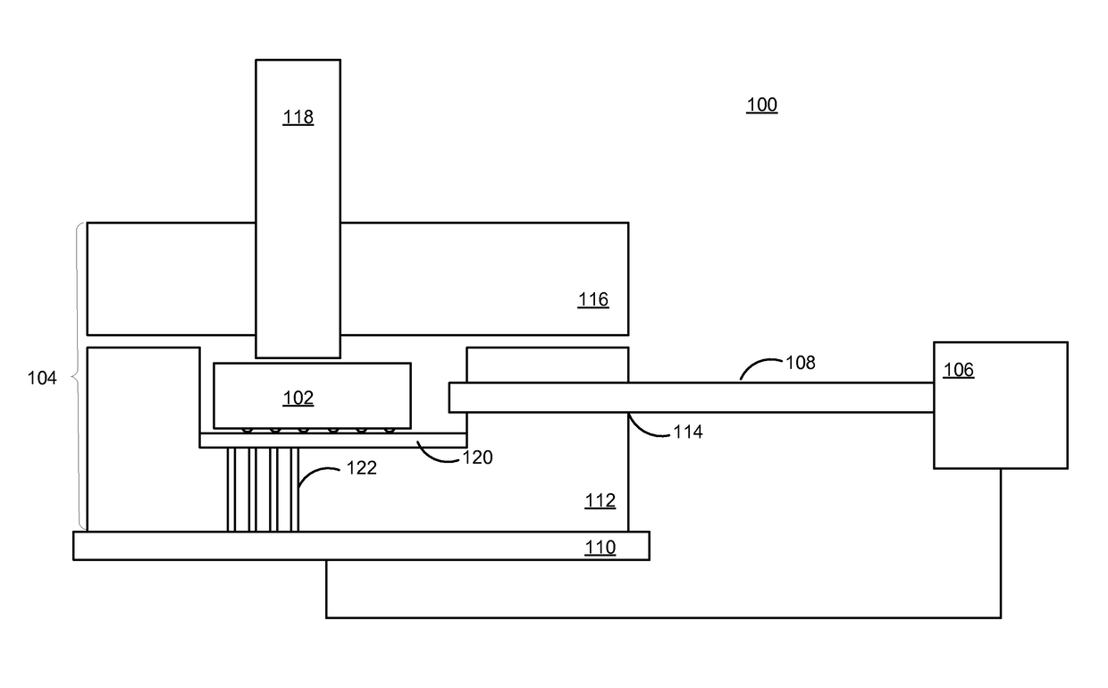
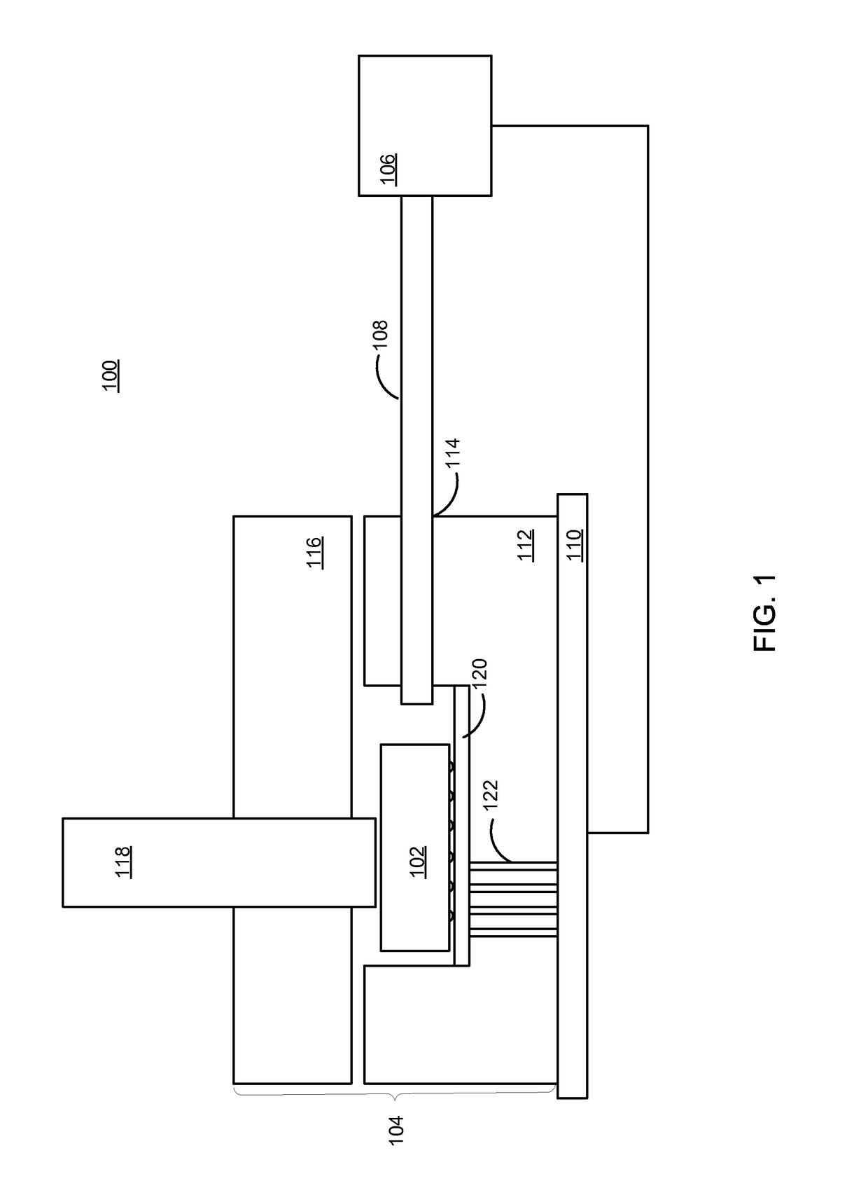
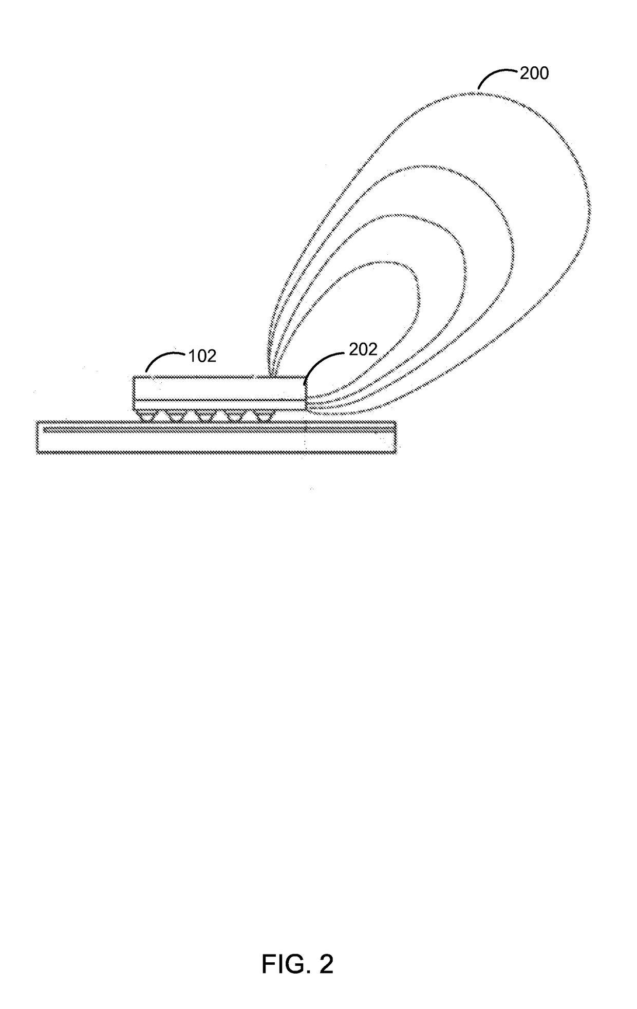
A test system includes a test socket assembly for capturing low energy electromagnetic emissions from radio frequency (RF) integrated circuits (ICs). The test socket assembly is structured to direct electromagnetic radiation from the device under test (DUT) to a socket port coupled to one end of a waveguide for transmission to a tester. The combination of the materials comprising the socket assembly is selected to more efficiently couple electromagnetic emissions from the DUT into the waveguide. For example, a reflective plane with an adjustable position may be located below the DUT in order to increase coupling of electromagnetic radiation from the DUT into the waveguide.

Description

BACKGROUND[0001]1. Technical Field[0002]This disclosure relates to a system for testing extremely high frequency (EHF) integrated circuits, and in particular for over-the-air testing of EHF integrated circuits in an automated test environment.[0003]2. Description of the Related Arts[0004]The adoption of wireless communication technologies continues to increase. Many of these devices employ radio frequency (RF) integrated circuits (ICs) that operate as transmitters, receivers, or transceivers that enable wireless intra and inter device communication. As demand for wireless communication enabled devices increases and a faster time to market becomes more important, the process of evaluating RF ICs becomes even more important.[0005]Systems for evaluating RF ICs include automated test equipment equipped to perform over-the-air testing of RF ICs. Examples of automated test systems used to evaluate RF ICs include wafer probe testing, automated test equipment (ATE), test fixtures using horn...

Claims


Application Information

Patent Timeline
IPC IPC(8): G01R1/04G01R31/28
CPCG01R31/2822G01R1/045G01R31/303G01R31/31905G01R31/69
Inventor SARHAD, BHUPENDRA SAKERLALSANSOM, CHRISTOPHER SCOTT
Owner KEYSSA
Learn More