System and method for controlling catheter power based on renal ablation response

a technology of renal ablation and catheter power, applied in the field of invasive medical devices, can solve the problems of global sympathetic denervation below the chest, resistance hypertension is a common clinical problem, and the blood pressure rises, so as to reduce the power level, and reduce the power level

Active Publication Date: 2017-04-20
BIOSENSE WEBSTER (ISRAEL) LTD
View PDF3 Cites 7 Cited by
  • Summary
  • Abstract
  • Description
  • Claims
  • Application Information

AI Technical Summary

Problems solved by technology

In hypertension, the continued release of low-dose amounts of these hormones can increase blood pressure.
Resistant hypertension is a common clinical problem faced by both primary care clinicians and specialists.
However, this procedure involves surgery and all its attendant risks, and often resulted in global sympathetic denervation below the chest.
However, unlike cardiac ablation, such feedback in renal ablation denervation does not readily provide information on acute end point indicating successful ablation.
That is, such feedback information does not readily help determine whether renal nerves have been impacted by the ablation.
However, renal arteries can be prone to exhibit physiological response during ablation.
However, with the increasing amount of ablation power, there is a greater risk for artery stenosis.
Renal artery stenosis is undesirable, if not dangerous, because narrowing of the renal arteries prevents normal amounts of oxygen-rich blood from reaching the kidneys which need adequate blood flow to help filter waste products and remove excess fluids.
Reduced blood flow may increase blood pressure and injure kidney tissue.

Method used


Image

  • System and method for controlling catheter power based on renal ablation response
  • System and method for controlling catheter power based on renal ablation response
  • System and method for controlling catheter power based on renal ablation response

Examples


Embodiment Construction

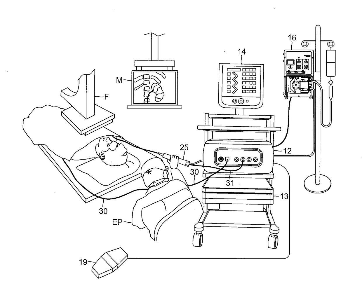
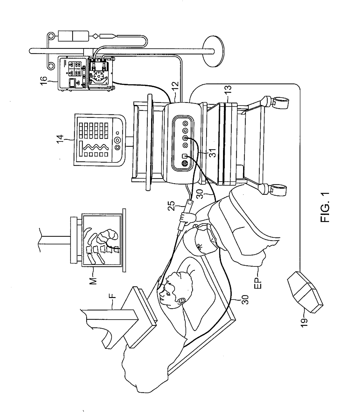
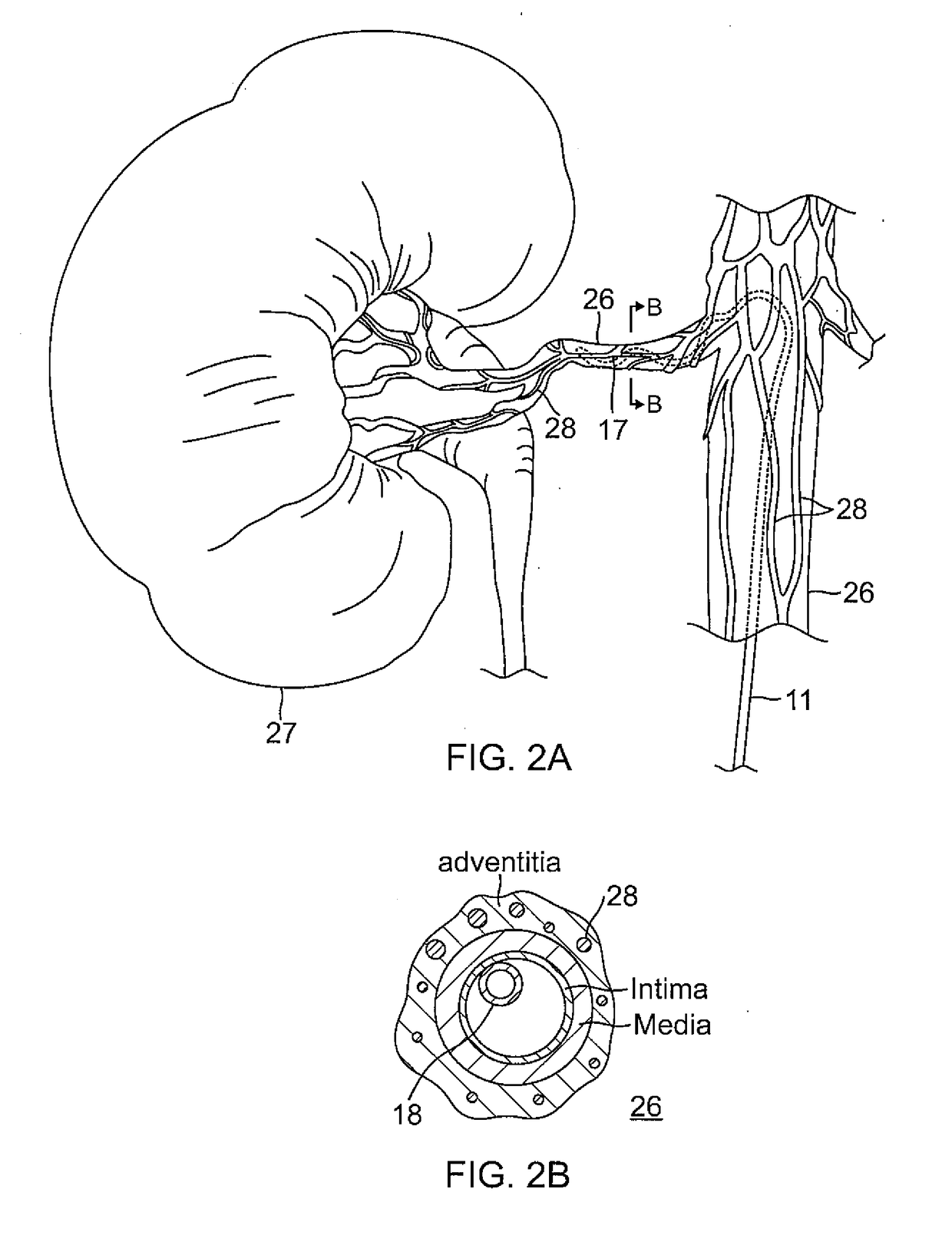
[0039]The present invention is directed to a catheter-based ablation system 10, with embodiments illustrated in FIG. 1, including a catheter 11, an RF generator console 12, a power supply 13, a display monitor 14, an irrigation pump 16, and an ablation actuator 19 (e.g., a foot pedal). The system 10 is adapted for renal ablation performed within a renal artery 26 near a kidney in denerving surrounding nerves 28, as shown in FIG. 2A and FIG. 2B. In some embodiments as shown in FIG. 3, the catheter 11 includes a control handle 25, a catheter body 15 and a helical distal portion 17 on which electrodes 18 are mounted, each adapted for contact with a different surface area of the inner circumferential tissue along the artery 26. As known in the art, the catheter enters the body of patient P via an opening in the femoral artery and is then advanced through the patient's vasculature by an electrophysiology professional EP under fluoroscopic guidance by means of a fluoroscope F and a monito...


PUM


Abstract

An ablation system observes and monitors ablation parameters, including temperature, impedance, and / or the system's own closed-loop response to these ablation parameters in delivery of power to one or more ablation electrodes, including cessation of power delivery to one or more electrodes while maintaining power delivery to one or more other electrodes. The system comprises a catheter with one or more electrodes and a detection circuitry configured to detect an ablation parameter for each electrode, a controller coupled to the catheter, the controller having a processing unit and a memory storing instructions that, when executed by the processing unit, cause the processing unit to: receive a detected ablation parameter for each electrode from the detection circuitry, control a power supplied to each violating electrode to have a reduced power when the respective detected ablation parameter violates a defined ablation parameter, detect a rate of power reduction for each violating electrode, and stop the power supplied to each violating electrode when a respective detected rate of power reduction exceeds a threshold rate of power reduction.

Description

FIELD OF INVENTION[0001]Aspects of embodiments of the present invention relate to invasive medical devices and associated control systems capable of ablation and sensing ablation responses, such as a catheter, and control systems capable of adjusting the power supplied to the catheter based on the sensed responses.BACKGROUND OF INVENTION[0002]Catheterization is used in diagnostic and therapeutic procedures. For example, a cardiac catheter is used for mapping and ablation in the heart to treat a variety of cardiac ailments, including cardiac arrhythmias, such as atrial flutter and atrial fibrillation which persist as common and dangerous medical ailments, especially in the aging population. Diagnosis and treatment of cardiac arrhythmias include mapping the electrical properties of heart tissue, especially the endocardium and the heart volume, and selectively ablating cardiac tissue by application of energy. Such ablation can cease or modify the propagation of unwanted electrical sign...

Claims


Application Information

Patent Timeline
Patent Type & Authority Applications(United States)
IPC IPC(8): A61B18/12A61B18/14
CPCA61B18/1233A61B34/25A61B2018/00577A61B2018/00511A61B2018/00654A61B2018/00648A61B2018/00678A61B2018/00708A61B2018/00779A61B2018/00791A61B2018/00875A61B2018/1467A61B2018/00886A61B2018/00672A61B2018/00434A61B18/1492A61B18/12A61B2018/00821A61B2018/00702A61B2018/00642A61B2018/00898A61B18/14A61B18/00
Inventor HIGHSMITH, DEBBY E.JIMENEZ, EDUARDOFUIMAONO, KRISTINE B.
Owner BIOSENSE WEBSTER (ISRAEL) LTD
Why Eureka
Try Eureka