Beam irradiation target confirmation device

a beam irradiation target and verification device technology, applied in tomography, applications, therapy, etc., can solve the problems of insufficient tumor dose, inability of ct imaging device to capture an image of the therapy patient lying in place, and inability to ensure the conditions of the therapy patient, etc., to achieve the effect of low exposure level

Active Publication Date: 2017-04-27
NAT INST FOR QUANTUM & RADIOLOGICAL SCI & TECH
View PDF28 Cites 2 Cited by
  • Summary
  • Abstract
  • Description
  • Claims
  • Application Information

AI Technical Summary

Benefits of technology

[0012]According to the present invention, there are provided a beam irradiation target verification apparatus, a beam irradiation target verification program, and a stopping-power-ratio calculation program, each capable of measuring internal conditions of a therapy patient and determining necessity of changing a therapy plan, easily and at a relatively low exposure level.

Problems solved by technology

Stopping of the particle beam at a location different from the location of a therapy plan may result in an insufficient dose in the tumor, and in a harmful event such as exposure of a critical organ.
However, due to its structure, a CT imaging device cannot capture an image of the therapy patient lying in place on the therapy patient support table of a particle beam therapy apparatus.
Thus, the conditions of the therapy patient may not necessarily be assured at the therapy location of the particle beam therapy apparatus.
Furthermore, performing CT imaging each time before a therapy causes an increase in the amount of exposure of the therapy patient during a therapy duration.
Thus, a method that performs CT imaging each time before a therapy poses a problem in that a change in shape etc. of the organ caused by a movement of the therapy patient cannot be handled, as well as a problem in that the amount of exposure increases.
However, a method using such carbon ion beam radiography needs acceleration of the carbon ion beam to an energy level sufficient for the carbon ion beam to pass through the therapy patient.
Thus, a method using such carbon ion beam radiography poses a problem in not being usable in a typical particle beam therapy facility in which a large-scale accelerator facility cannot be installed.
In addition, a method using carbon ion beam radiography also poses a problem in involving an impractically long period of time and an unacceptable level of exposure in order to obtain an image with sufficiently high accuracy.

Method used


Image

  • Beam irradiation target confirmation device
  • Beam irradiation target confirmation device
  • Beam irradiation target confirmation device

Examples


embodiment 1

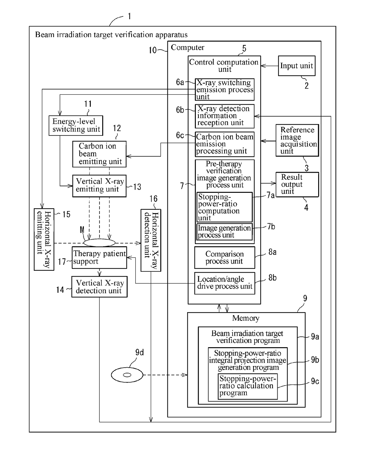
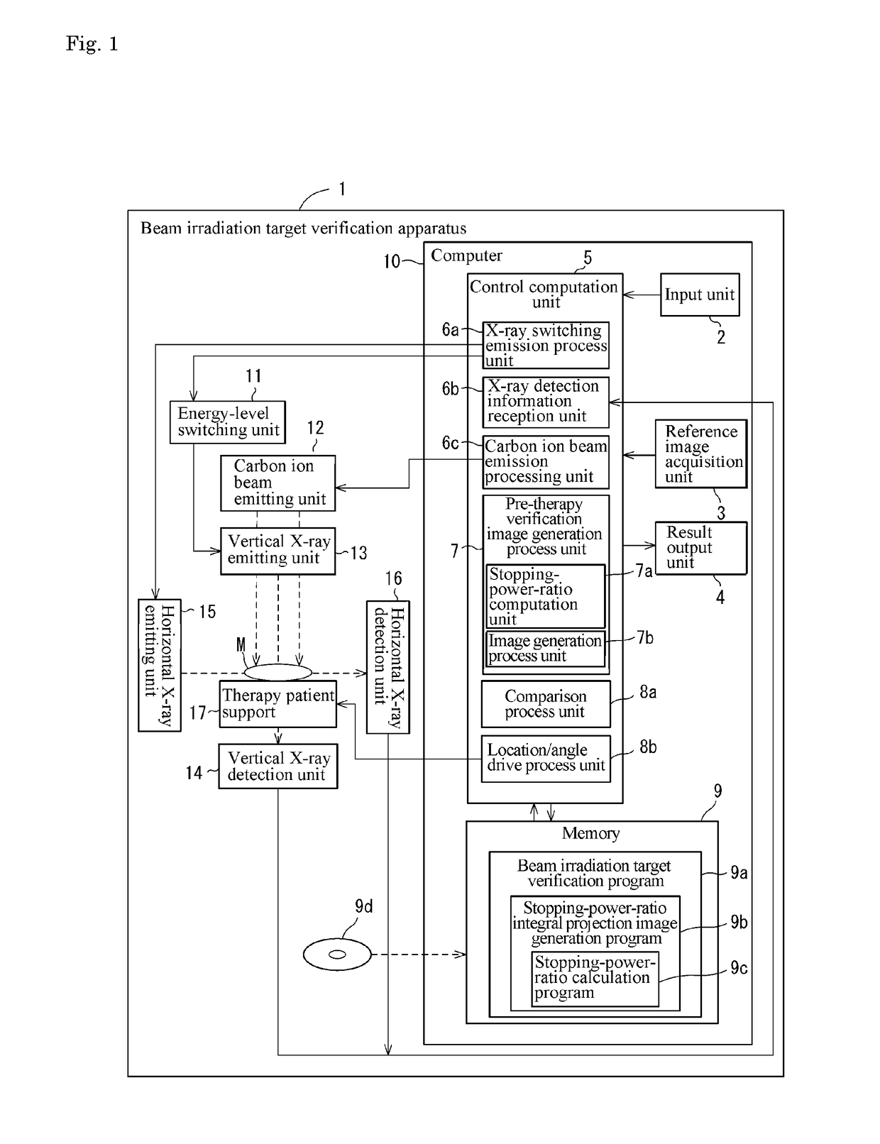
[0017]FIG. 1 is a block diagram illustrating a configuration of a beam irradiation target verification apparatus 1. The beam irradiation target verification apparatus 1 includes a computer 10, an energy-level switching unit 11, a carbon ion beam emitting unit 12, a vertical X-ray emitting unit 13 (X-ray emitting unit), a vertical X-ray detection unit 14 (X-ray detection unit), a horizontal X-ray emitting unit 15, a horizontal X-ray detection unit16, and a therapy patient support 17.

[0018]The computer 10 includes an input unit 2, a reference image acquisition unit 3, a result output unit 4, a control computation unit 5, and a memory 9. The control computation unit 5 includes an X-ray switching emission process unit 6a, an X-ray detection information reception unit 6b, a carbon ion beam emission process unit 6c, a pre-therapy verification image generation process unit 7, a comparison process unit 8a, and a location / angle drive process unit 8b.

[0019]The input unit 2 receives an input ...


PUM


Abstract

A beam irradiation target verification apparatus (1) includes an X-ray switching emission process unit (6a) that causes a vertical X-ray emitting unit (13) to emit at least two types of X-rays using an energy-level switching unit (11), a vertical X-ray detection unit (14) that detects an X-ray emitted from the vertical X-ray emitting unit (13), a pre-therapy verification image generation process unit (7) that generates pre-therapy verification images (20B) and (20C) based on detection information on at least two types of X-rays obtained by the vertical X-ray detection unit (14), a reference image acquisition unit (3) that acquires a reference image (20A) obtained at a therapy planning stage, a comparison process unit (8a) that makes comparisons between the pre-therapy verification images (20B) and (20C) and the reference image (20A), and a result output unit (4) that outputs a comparison result obtained by the comparison process unit (8a). Thus, there is provided a beam irradiation target verification apparatus for therapeutic purposes capable of measuring internal conditions of a therapy patient and determining necessity of changing a therapy plan, easily and at a relatively low exposure level.

Description

TECHNICAL FIELD[0001]The present invention relates to a beam irradiation target verification apparatus, for example, for use prior to a particle beam therapy, to a beam irradiation target verification program, and to a stopping-power-ratio calculation program.BACKGROUND ART[0002]Conventionally, a particle beam therapy apparatus typically for proton beam therapy or carbon ion beam therapy has been utilized. Such a particle beam therapy apparatus exploits a feature that allows a particle beam to emit energy in a focused manner at a stopping location (i.e., at or near the end of travel), and is thus adjusted before use so that the particle beam will stop at the location of a tumor. Thus, the particle beam therapy apparatus achieves reduction in exposure of normal tissue, and at the same time, causes damage on the tumor in a focused manner. If the location, size, shape or the like of the tumor differs between those at the time of therapy planning and those at the time of therapy, the pa...

Claims


Application Information

Patent Timeline
Patent Type & Authority Applications(United States)
IPC IPC(8): A61N5/10A61B6/00A61B6/03
CPCA61N5/1039A61B6/563A61B6/032A61N5/1077A61B6/482A61B6/5217A61B6/5235A61N5/103A61N5/1049A61N5/1069A61N2005/1061A61N5/1065A61N2005/1087G16H50/30
Inventor INANIWA, TAKUFURUKAWA, TAKUJINODA, KOJI
Owner NAT INST FOR QUANTUM & RADIOLOGICAL SCI & TECH
Why Eureka
Try Eureka