Wireless power supply system and wireless power reception device

a technology of wireless power supply and wireless power reception, which is applied in the direction of charging stations, battery/cell propulsion, transportation and packaging, etc., can solve the problem of taking a long time before the vehicle is actually charged

Active Publication Date: 2017-04-27
NISSAN MOTOR CO LTD
View PDF16 Cites 8 Cited by
  • Summary
  • Abstract
  • Description
  • Claims
  • Application Information

AI Technical Summary

Benefits of technology

[0004]However, in the configuration in the conventional example disclosed in above Patent Literature 1, in order to perform the pairing, the vehicle enters and stops in the parking space, and in this state a signal containing a random ID pattern is transmitted by the power transmission coil and received by the vehicle. For this reason, a problem arises in that it takes a long time before the vehicle starts to be actually charged after stopping in the parking space.
[0005]The present invention has been made to solve this problem in the conventional art, and an object thereof is to provide a wireless power supply system and a wireless power reception device capable of quick pairing with a vehicle entering a parking space.
[0006]A wireless power supply system according to one aspect of the present invention includes a power transmission device provided on the ground and a power reception device provided to a vehicle. The power transmission device includes a power transmission coil configured to transmit power, a power-supply control unit configured to control power to be supplied to the power transmission coil, and a power-transmission-side communication unit configured to communicate with the power reception device. Also, the power reception device includes a power reception coil configured to receive power transmitted from the power transmission coil and supply the received power to an electric load through a capacitor, a power-reception control unit configured to control power reception of the power reception coil, and a power-reception-side communication unit configured to communicate with the power transmission device. When the vehicle approaches a parking space, the power-supply control unit sets the power transmission coil to first excitation in which the power transmission coil is excited in an excitation pattern containing identification data. The power-reception control unit pre-charges the capacitor after the vehicle approaches the parking space, acquires the identification data when the power transmission coil is in the first excitation, and transmits the acquired identification data to the power transmission device. The power-supply control unit pairs the power transmission device and the power reception device with each other if the identification data contained in the excitation pattern and the identification data acquired by the power-reception control unit match each other.
[0007]A wireless power reception device according to one aspect of the present invention includes: a power reception coil configured to receive power transmitted from a power transmission device and supply the received power to an electric load through a capacitor; a power-reception control unit configured to control power reception of the power reception coil, and a power-reception-side communication unit configured to communicate with the power transmission device. The power-reception control unit pre-charges the capacitor when the vehicle approaches a parking space, acquires identification data when a power transmission coil provided to the power transmission device is being excited in an excitation pattern containing the identification data, and transmits the acquired identification data to the power transmission device.

Problems solved by technology

For this reason, a problem arises in that it takes a long time before the vehicle starts to be actually charged after stopping in the parking space.

Method used


Image

  • Wireless power supply system and wireless power reception device
  • Wireless power supply system and wireless power reception device
  • Wireless power supply system and wireless power reception device

Examples


first embodiment

Description of First Embodiment

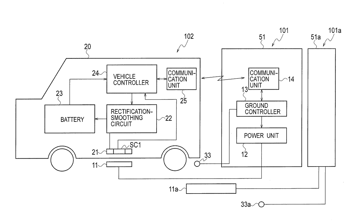
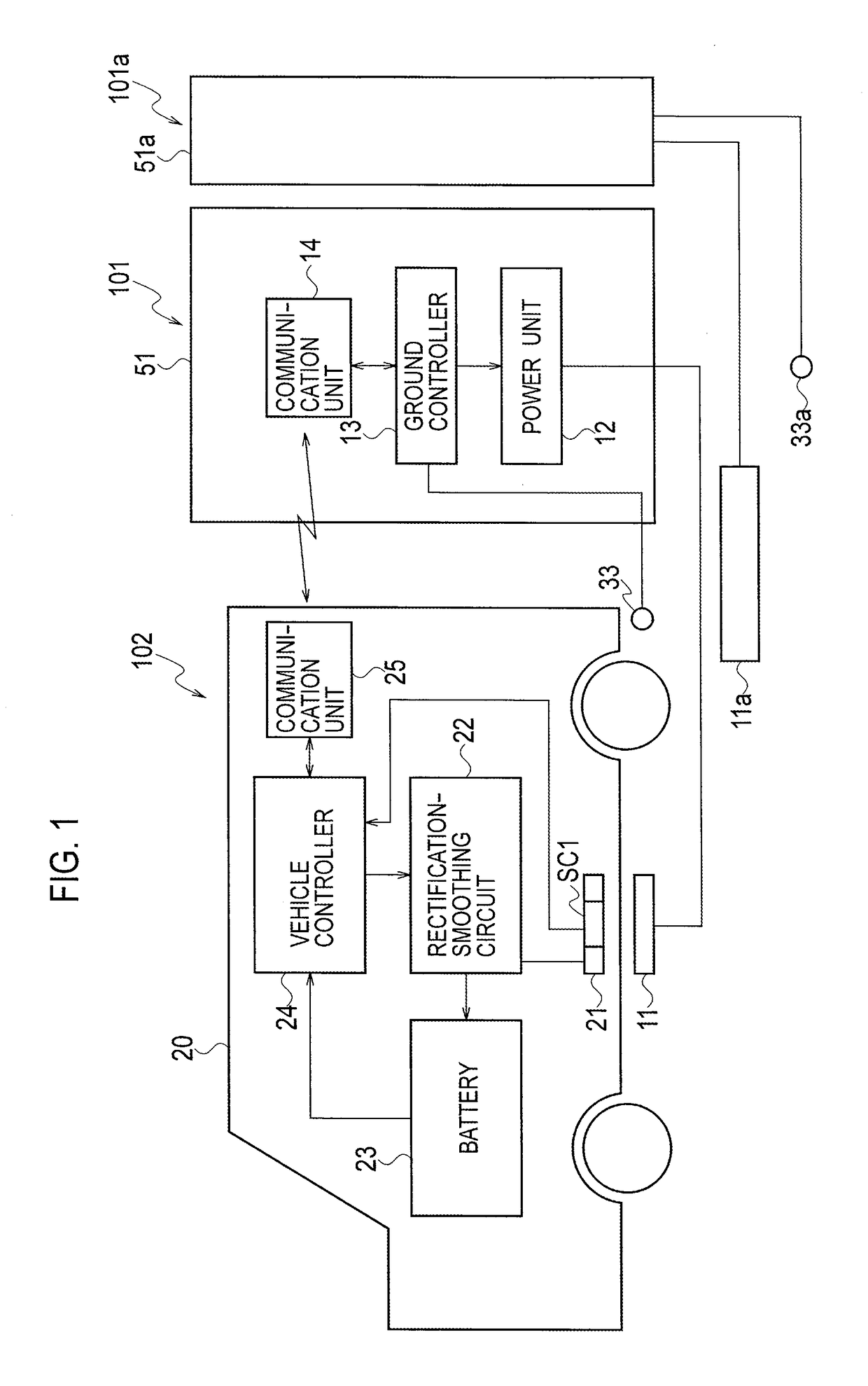
[0037]FIG. 1 is a block diagram showing the configuration of a wireless power supply system according to a first embodiment of the present invention. As shown in FIG. 1, this wireless power supply system includes a plurality of power transmission devices (two power transmission devices 101, 101a are shown in FIG. 1 as an example) provided to parking equipment on the ground, and a power reception device 102 mounted on a vehicle 20.

[0038]The power transmission device 101 includes a parking space for parking the vehicle 20. The power transmission device 101 also includes a ground unit 51, a power transmission coil 11 installed on the ground of the parking space, and a vehicle detection sensor 33 configured to detect when the vehicle 20 approaches the parking space. Note that FIG. 1 shows the two power transmission devices 101, 101a as an example. The present invention is not limited to this case, but is applicable to cases where three or more power transm...

second embodiment

Description of Second Embodiment

[0083]Next, a second embodiment will be described. In the above-described first embodiment, the description has been given of the example where the power reception device 102 and the power transmission device 101 are paired with each other based on a pairing signal received by the subcoil SC1. In the second embodiment, the subcoil SC1 is not mounted, and the power reception coil 21 receives a pairing signal and the power reception device 102 and the power transmission device 101 are paired with each other based on this pairing signal.

[0084]FIG. 16 is a block diagram showing the configuration of a wireless power supply system according to the second embodiment. FIG. 17 is a circuit diagram showing detailed configurations of the power unit 12, the power transmission coil 11, the power reception coil 21, and the rectification-smoothing circuit 22 shown in FIG. 16 and peripheral elements thereof. Also, FIG. 18 is an explanatory diagram showing the power r...

third embodiment

Description of Third Embodiment

[0091]Next, a third embodiment will be described. In the above-described first embodiment, the description has been given of the example where the subcoil SC1, provided by the power reception coil 21, is used to receive a pairing signal transmitted from the power transmission coil 11 and pair the power reception device 102 and the power transmission device 101 with each other. In contrast, in the third embodiment, a plurality of subcoils are mounted, and each subcoil is used to receive a pairing signal so as to perform quick pairing. Also, after the pairing is completed, the capacitor C3 is pre-charged so as to quickly perform positioning by means of the second excitation. Details will be described below.

[0092]FIG. 19 is a block diagram showing the configuration of a wireless power supply system according to the third embodiment. As shown in FIG. 19, the wireless power supply system according to the third embodiment differs from that in the above-descr...


PUM


Abstract

When a vehicle approaches a parking space, a ground controller sets a power transmission coil to first excitation in which the power transmission coil is excited in an excitation pattern containing identification data. A vehicle controller pre-charges a capacitor connected to a power reception coil after the vehicle approaches the parking space. Further, the vehicle controller acquires the identification data when the power transmission coil is in the first excitation, and transmits the acquired identification data to the ground unit. The ground controller pairs a power transmission device and a power reception device with each other if the identification data contained in the excitation pattern and the identification data acquired by the vehicle controller match each other.

Description

TECHNICAL FIELD[0001]The present invention relates to a wireless power supply system and a wireless power reception device for wirelessly supplying power to a vehicle equipped with an electric load such as a battery.BACKGROUND ART[0002]Heretofore, a wireless charge system disclosed in Patent Literature 1 has been known which is configured to wirelessly supply power to a vehicle equipped with a battery (electric load) to charge the battery. This Patent Literature 1 discloses that, in a case where a plurality of power transmission devices are present, a power transmission coil is weakly excited to generate a random signal, which is detected by a vehicle, and the vehicle and the power transmission device are paired with each other if it is confirmed that the random signals match each other between the vehicle and the power transmission device.CITATION LISTPatent Literature[0003]Patent Literature 1: International Publication No. WO2012 / 042902SUMMARY OF INVENTION[0004]However, in the con...

Claims


Application Information

Patent Timeline
Patent Type & Authority Applications(United States)
IPC IPC(8): B60L11/18H02J50/40H02J50/10
CPCB60L11/182B60L11/1824H02J50/40H02J50/10H02J50/80H02J50/90H02J7/00B60L50/50B60L53/30B60L53/122B60L53/126Y02T10/70Y02T90/16Y02T90/12Y02T10/7072Y02T90/14H02J50/12H02J50/402H02J2310/48B60L53/38B60L53/65B60L53/305Y04S30/14H01F38/14
Inventor TSUKAMOTO, YUKINORI
Owner NISSAN MOTOR CO LTD
Why Eureka
Try Eureka