Time-of-flight distance measurement device and method for same

a technology of time-of-flight distance measurement and time-of-flight, applied in the direction of measurement devices, using reradiation, instruments, etc., to achieve the effect of reducing noise components, reducing distance errors, and increasing signal components

Active Publication Date: 2017-04-27
DENSO CORP
View PDF6 Cites 23 Cited by
  • Summary
  • Abstract
  • Description
  • Claims
  • Application Information

AI Technical Summary

Benefits of technology

[0011]The present disclosure has been made in view of the above issues, and an object of the present disclosure is to provide a time-of-flight distance measurement device and a method for the device, which are capable of appropriately reducing a distance error without increasing a light emission power, using an optical filter, increasing the number of integrations, and increasing a modulation frequency.
[0013]According to the first aspect, in calculation of the distance to the object, because the component of the fundamental wave is linearly combined with at least one high-order harmonic, the distance error can be appropriately reduced more than a case in which the distance is measured on the basis of only the component of the fundamental wave as much as the consideration of the high-order harmonic component. In that case, there is no need to increase the light emission power in order to increase the signal component, there is no need to use an optical filter in order to reduce a noise component, there is no need to increase the number of integrations, and there is no need to increase the modulation frequency. In other words, the distance error can be appropriately reduced without increasing the light emission power, using the optical filter, increasing the number of integrations, and increasing the modulation frequency.
[0015]According to the second aspect, as in the first embodiment, in the calculation of the distance to the object, the component of the fundamental wave is linearly combined with the component of at least one high-order harmonic. For that reason, the distance error can be appropriately reduced more than a case in which the distance is calculated on the basis of only the component of the fundamental wave as much as the consideration of the high-order harmonic component. In that case, there is no need to increase the light emission power in order to increase the signal component, there is no need to use an optical filter in order to reduce a noise component, there is no need to increase the number of integrations, and there is no need to increase the modulation frequency. In other words, the distance error can be appropriately reduced without increasing the light emission power, using the optical filter, increasing the number of integrations, and increasing the modulation frequency.

Problems solved by technology

However, in a method of increasing the light emission power, attention is paid to a power consumption and a heat generation caused by the power consumption.

Method used


Image

  • Time-of-flight distance measurement device and method for same
  • Time-of-flight distance measurement device and method for same
  • Time-of-flight distance measurement device and method for same

Examples


Embodiment Construction

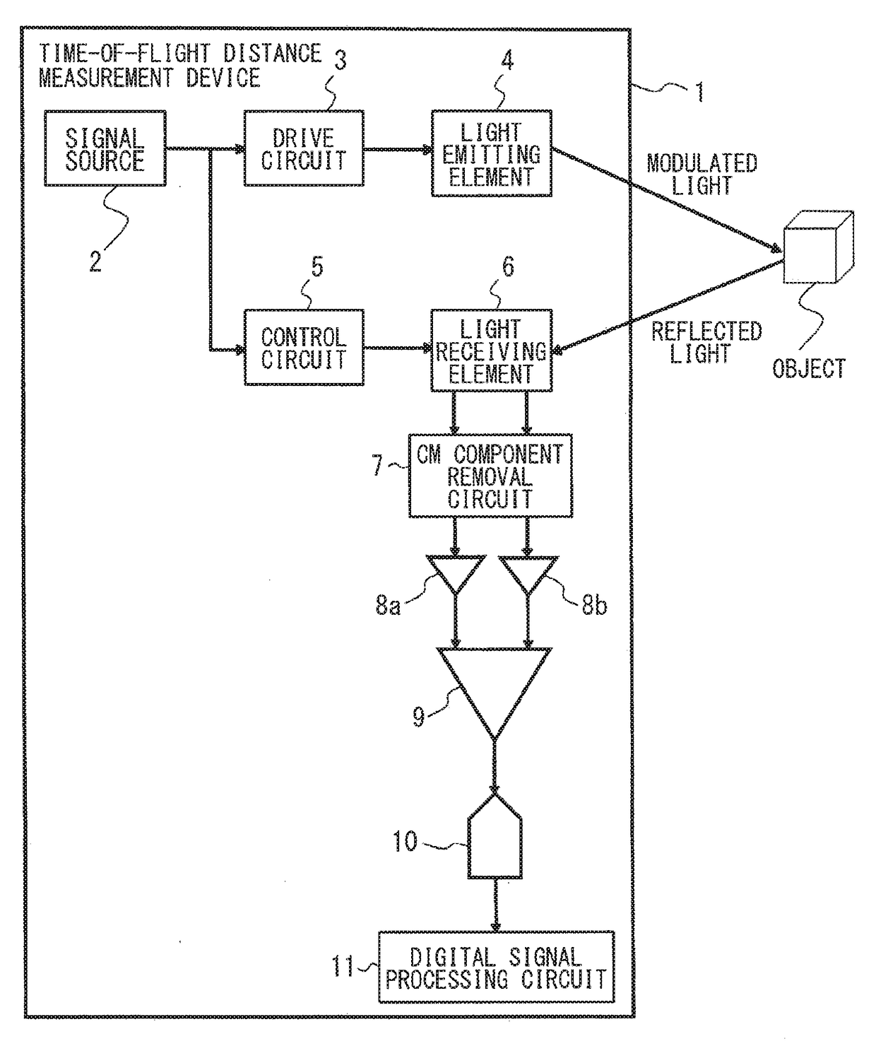
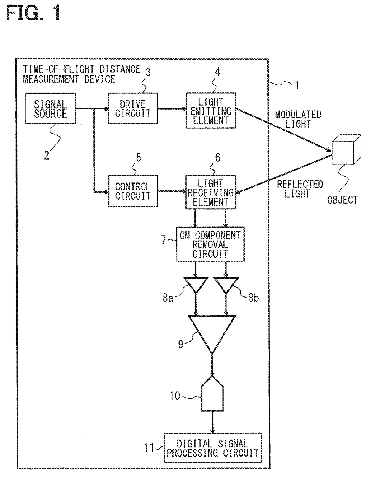
[0039]Hereinafter, an embodiment, in which a time-of-flight distance measurement device and a time-of-flight distance measurement method according to the present disclosure are applied to, for example, a vehicle, will be described with reference to the drawings. An object, a distance of which from the subject device is measured, is, for example, a person, a vehicle, a wall, and the like. A time-of-flight distance measurement device 1 includes a signal source 2, a drive circuit 3 (drive unit), a light emitting element 4, a control circuit 5 (control unit), a light receiving element 6, a CM (common mode) component removal circuit 7, buffers 8a, 8b, a differential detection circuit 9, an AD conversion circuit 10, and a digital signal processing circuit 11 (signal processing unit).

[0040]The signal source 2 outputs a drive signal to the drive circuit 3 and the control circuit 5 to establish a synchronization between the light emitting element 4 and the light receiving element 6 and contr...


PUM


Abstract

A light emitting element emits a modulated light modulated in a pattern having a repetitive period toward a space. A driving unit drives the light emitting element. A light receiving element distributes charges corresponding to an incident light containing a reflected light obtained by reflecting the modulated light on an object to storage capacitors and stores the distributed charges. A control unit controls an exposure of the light receiving element. A signal processing unit measures a distance to the object by using a value sampled by the light receiving element. The control unit controls the exposure of the light receiving element to give a sensitivity to at least one high-order harmonic. The signal processing unit linearly combines a component of a fundamental wave with a component of the at least one high-order harmonic to measure the distance to the object.

Description

CROSS REFERENCE TO RELATED APPLICATION[0001]This application is based on Japanese Patent Application No. 2014-226069 filed on Nov. 6, 2014, the disclosure of which is incorporated herein by reference.TECHNICAL FIELD[0002]The present disclosure relates to a time-of-flight distance measurement device and a method for the device, which emit a modulated light modulated in a pattern having a repetitive period toward a space, receive an incident light containing a reflected light obtained by reflecting the modulated light on an object to distribute charges to multiple storage capacitors and accumulate the distributed charges, and measure a distance from the subject device to the object by using a sampled value.BACKGROUND ART[0003]As a device for measuring a distance from a subject device to an object without contact, a time of flight (TOF: time of flight) distance measurement device is provided. The time-of-flight distance measurement device emits a modulated light (distance measuring lig...

Claims


Application Information

Patent Timeline
Patent Type & Authority Applications(United States)
IPC IPC(8): G01S17/10G01S7/486G01S7/4861G01S7/4865G01S17/894
CPCG01S17/10G01S7/4861G01S7/4868G01S7/4865G01S17/894
Inventor NAGAI, TOSHIAKIYANAI, KENICHI
Owner DENSO CORP
Why Eureka
Try Eureka