Switching Power Supply Circuit

a power supply circuit and flip-flop technology, applied in the direction of power conversion systems, instruments, dc-dc conversion, etc., can solve the problems of transient response deterioration, etc., to avoid unstable output voltage vout actions, load stability can be enhanced, and gain can be increased

Active Publication Date: 2017-04-27
TOREX SEMICON LTD
View PDF0 Cites 8 Cited by
  • Summary
  • Abstract
  • Description
  • Claims
  • Application Information

AI Technical Summary

Benefits of technology

[0034]With the present invention, an error signal amplified by the error amplifier is inputted to the comparator, and thus the gain can be increased. Consequently, the load stability can be enhanced.
[0035]Also, the integration circuit is connected in parallel to the inductance coil, whereby a voltage waveform similar to the ripple voltage contained in the output voltage can be generated at the junction between the first resistor and the first capacitor. Moreover, the above voltage is applied to the input side of the comparator via the second capacitor. Thus, the comparator is supplied with sufficient ripple information. Consequently, unstable actions of the output voltage VOUT can be avoided.
[0036]Hence, there can be provided a switching power supply circuit of a PFM control type which can utilize a capacitor with low ESR, such as a ceramic capacitor, as load capacity, can operate stably even at an oscillation frequency of several MHz or more, obtains high load stability, and can reduce the layout area.

Problems solved by technology

If the ripple component of the output voltage VOUT is small, therefore, switching control in the flip-flop circuit 2 becomes unstable.
Consequently, the output voltage VOUT shows an unstable action, such as including undulations.
As a result, if the amplitude is great, a transient response will deteriorate.
Thus, the problem arises that current consumption increases significantly, and because of a small DC gain, load stability lowers.
Moreover, a phase shift occurs owing to a response delay of the comparator 1, and stable operation may fail to be performed.
Both of these switching power supply circuits, however, pose the problem that load stability deteriorates.
However, this requires a very large layout area.

Method used


Image

  • Switching Power Supply Circuit
  • Switching Power Supply Circuit
  • Switching Power Supply Circuit

Examples


Embodiment Construction

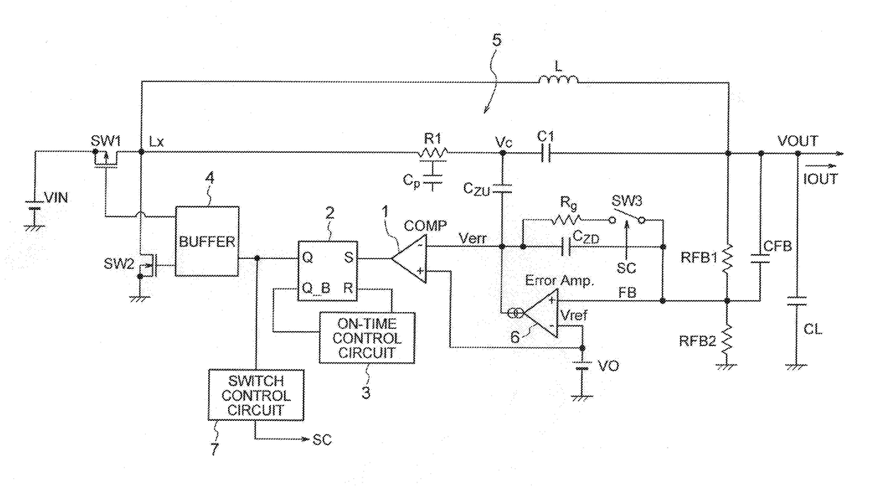
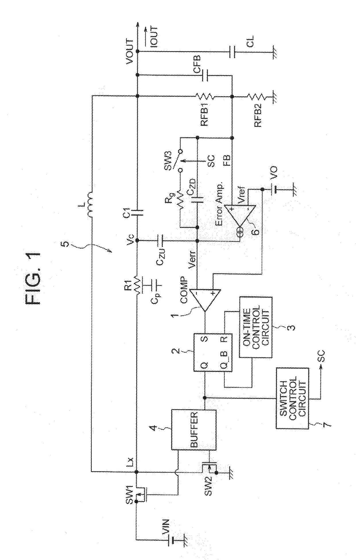
[0040]The embodiment of the present invention will now be described in detail with reference to the accompanying drawings. FIG. 1 is a circuit diagram showing the switching power supply circuit of the present invention. As shown in this drawing, the switching power supply circuit according to the present embodiment has a main switching element SW1 connected to an input power source VIN, and a subordinate switching element SW2 connected to the main switching element SW1 via a connection point Lx, and turns the main and subordinate switching elements SW1 and SW2 on or off alternately. The switching power supply circuit is a DC / DC converter in a PFM control mode which, by such a mechanism, converts a direct current input voltage into a direct current output voltage VOUT via an inductance coil L. The output voltage VOUT is smoothed by a capacitor with low ESR such as a ceramic capacitor.

[0041]A comparator 1 compares the output voltage of an error amplifier 6 with a reference voltage Vre...


PUM


Abstract

A switching power supply circuit includes: an error amplifier for amplifying a deviation between a reference voltage and a feedback voltage; a comparator for comparing the reference voltage with an output voltage of the error amplifier, and outputting a predetermined set signal; an ON-time control circuit for defining a period during which a switching element is ON; a flip-flop circuit which is set by the set signal to bring the switching element into an ON- or OFF-state, and is reset by an output signal of the ON-time control circuit to bring the switching element into an OFF- or ON-state; a ripple voltage detection circuit for connecting an integration circuit in parallel to an inductance coil, thereby detecting a ripple voltage contained in the output voltage; and a capacitor connected between the output side of the error amplifier and a junction of a resistor and a capacitor of the integration circuit.

Description

CROSS-REFERENCE TO RELATED APPLICATION[0001]This application claims priority to Japanese Patent Application No. 2015-208868 filed Oct. 23, 2015, the disclosure of which is hereby incorporated in its entirety by reference.TECHNICAL FIELD[0002]This invention relates to a switching power supply circuit and, more specifically, to that useful when applied to a DC / DC converter.BACKGROUND ART[0003]As a switching power supply circuit capable of high speed operation, a proposal has been made for the one configured to adjust an output voltage by turning on or off a switching element with the use of the output of a flip-flop circuit, as shown in FIG. 3. As shown in this drawing, this switching power supply circuit is equipped with a comparator 1 which compares a feedback voltage FB based on an output voltage VOUT (i.e., a voltage obtained by dividing the output voltage VOUT by a resistance ratio between the resistances of feedback resistors RFB1 and RFB2) with a reference voltage Vref as the o...

Claims


Application Information

Patent Timeline
Patent Type & Authority Applications(United States)
IPC IPC(8): H02M3/158H02M1/08
CPCH02M3/158H02M2001/0009H02M1/08H02M3/156H02M1/0009
Inventor HANE, NORIMASA
Owner TOREX SEMICON LTD
Why Eureka
Try Eureka