Device for release of reactant into the exhaust gas stream of an internal combustion engine

a technology of reactant and exhaust gas, which is applied in the direction of machines/engines, mechanical equipment, separation processes, etc., can solve the problem of not being able to achieve a sufficient evaporation of reactan

a technology of reactant and exhaust gas, which is applied in the direction of machines/engines, mechanical equipment, separation processes, etc., can solve the problem of not being able to achieve a sufficient evaporation of reactan

US20170122167A1Active Publication Date: 2017-05-04PUREM GMBH

Image

  • Device for release of reactant into the exhaust gas stream of an internal combustion engine
  • Device for release of reactant into the exhaust gas stream of an internal combustion engine

Examples


Embodiment Construction

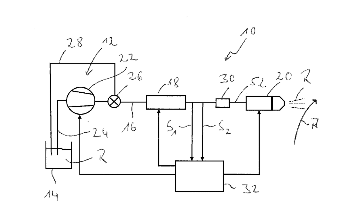
[0029]Referring to the drawings, a device for releasing reactant into the exhaust gas stream of an internal combustion engine is generally designated by 10 in FIG. 1. The device 10 comprises a reactant delivery unit 12, by means of which reactant R can be taken from a reactant reservoir 14, i.e., for example, from a storage container, and be delivered via a reactant line 16 to a, for example, electrically energizable heating unit 18. In the heating unit 18, the reactant R delivered by means of the reactant delivery unit 12 and pressurized is heated to an overheating temperature and further delivered to a reactant injection unit 20. The reactant R is released and injected by means of the reactant injection unit into the schematically shown exhaust gas stream A, which is routed in an exhaust gas-carrying duct of an exhaust system of an internal combustion engine.

[0030]The reactant delivery unit 12 comprises a reactant pump 22, which receives the reactant R from the reactant reservoir ...


PUM

PropertyMeasurementUnit
temperatureaaaaaaaaaa
pressureaaaaaaaaaa
vapor pressureaaaaaaaaaa

Abstract

A device for releasing reactant (R) into the exhaust gas stream (A) of an internal combustion engine includes a reactant injection unit (20), a reactant delivery unit (12) for delivering reactant (R) from a reactant reservoir (14) to the reactant injection unit (20), a heating unit (18) for heating reactant (R) delivered by the reactant delivery unit (12) to the reactant injection unit (20). An actuating unit (32) actuates the reactant delivery unit (12), the heating unit (18) and the reactant injection unit (20). An overpressure valve (26) or / and a pressure storage unit (30) is provided downstream of the reactant delivery unit (12).

Description

CROSS REFERENCE TO RELATED APPLICATIONS[0001]This application claims the benefit of priority under 35 U.S.C. ยง119 of German Application 10 2015 118 572.5 filed Oct. 30, 2015, the entire contents of which are incorporated herein by reference.FIELD OF THE INVENTION[0002]The present invention pertains to a device for the release of reactant into the exhaust gas stream of an internal combustion engine, comprising a reactant injection unit, a reactant delivery unit for delivering reactant from a reactant reservoir to the reactant injection unit, a heating unit for heating reactant delivered by the reactant delivery unit to the reactant injection unit, as well as an actuating unit for actuating the reactant delivery unit, the heating unit and the reactant injection unit.BACKGROUND OF THE INVENTION[0003]A device for releasing reactant into the exhaust gas stream of an internal combustion engine is well known from DE 10 2006 049 591 A1. The reactant to be released by this device is a urea s...

Claims


Application Information

Patent Timeline
04 May 2017
Publication
US20170122167A1
IPC
F01N3/20; B01D53/94; F01N3/28; B01D53/90
CPC
F01N3/208; B01D53/90; B01D53/9431; F01N2610/105; B01D2251/2067; B01D2257/40; F01N3/2896; F01N3/2066
Inventors
GAISER, GERD