Turbine blade and aircraft engine comprising same

a technology of turbine blades and aircraft engines, which is applied in the field of turbine blades, can solve the problems of insufficient creep resistance and tensile strength of materials currently employed for the blades of the first stage of a low pressure turbine, further increase in thermal and mechanical stress of components, and achieve the effects of improving the segregation behavior of alloys (b), improving the distribution of w, and reducing casting segregation

Active Publication Date: 2017-05-04
MTU AERO ENGINES GMBH
View PDF12 Cites 3 Cited by
  • Summary
  • Abstract
  • Description
  • Claims
  • Application Information

AI Technical Summary

Benefits of technology

[0065]The above alloys (b) are characterized by a weight ratio Ta:Al of from 1:1 to 2:1 because it has been observed that weight ratios in this range can improve the distribution of W and Mo between the γ matrix and the γ′ precipitates, resulting in a concentration of W and/or Mo in the γ matrix which is higher than the concentration of W and/or Mo in the γ′ precipitates.
[0066]Further, a weight ratio Co:W of from 2:1 to 5:1 usually makes it possible to achieve an improvement of the segregat...

Problems solved by technology

The materials currently employed for the blades of the first stage of a low pressure turbine are disadvantageous in that in the case of blades rotating at high speed or with high gas loads in the case of stationary vanes the creep resistance and tensile strength of these materials above about 1100° C. is insufficient.
This causes a further increase in the thermal and mechanical stress of the components, in particular of the rotating blades and the stationary vanes of the first stage...

Method used


Image

  • Turbine blade and aircraft engine comprising same
  • Turbine blade and aircraft engine comprising same

Examples


Embodiment Construction

[0100]The particulars shown herein are by way of example and for purposes of illustrative discussion of the embodiments of the present invention only and are presented in the cause of providing what is believed to be the most useful and readily understood description of the principles and conceptual aspects of the present invention. In this regard, no attempt is made to show details of the present invention in more detail than is necessary for the fundamental understanding of the present invention, the description in combination with the drawing making apparent to those of skill in the art how the several forms of the present invention may be embodied in practice.

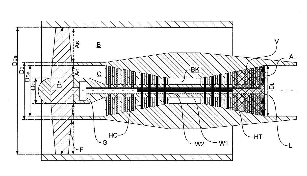
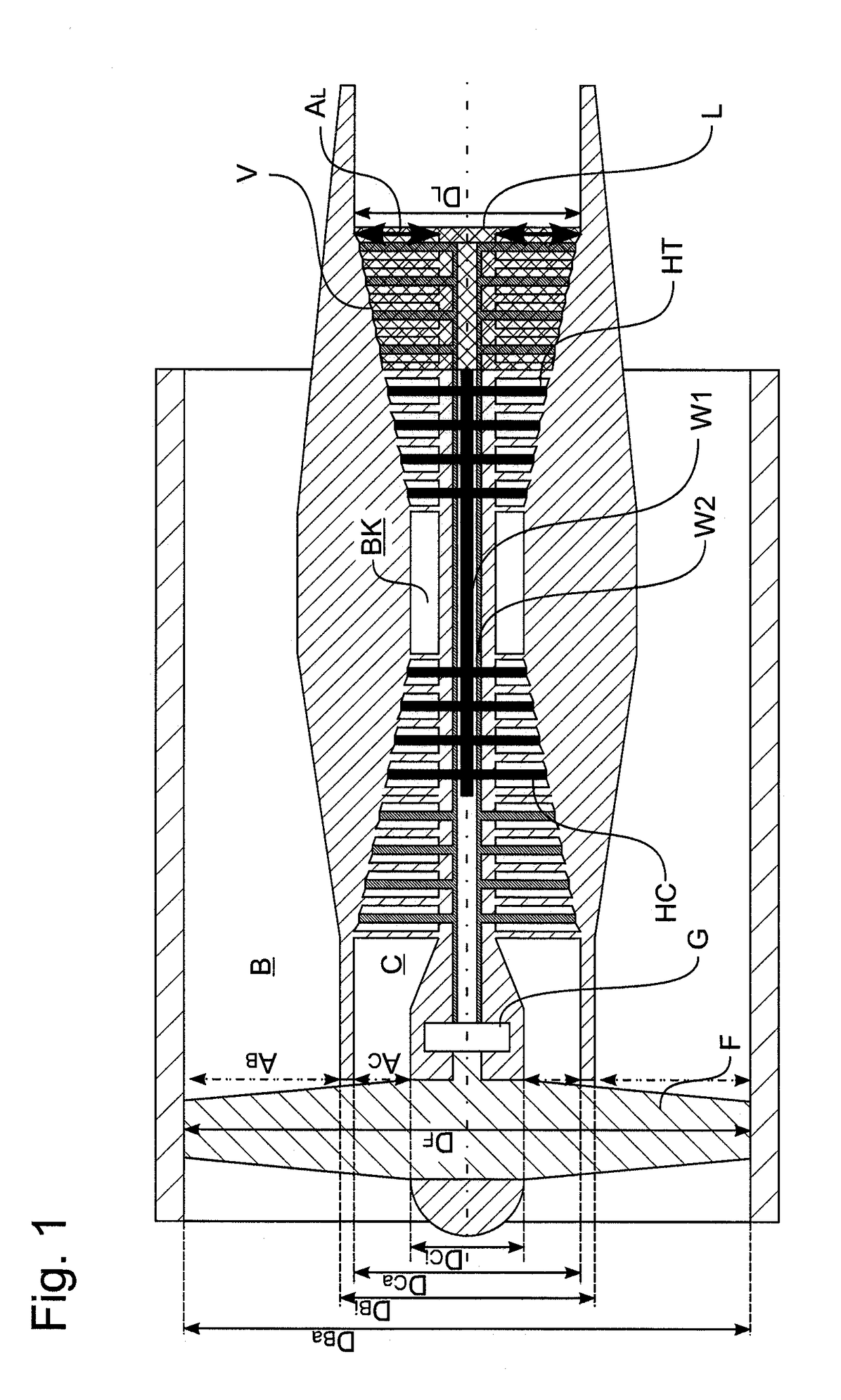
[0101]FIG. 1 depicts a turbofan aircraft engine of a passenger jet in accordance with an embodiment of the present invention. The engine has a primary duct C containing a combustion chamber BK. The primary duct has a first turbine or high-pressure turbine HT, which is located immediately downstream (to the right in FIG. 1) ...


PUM

PropertyMeasurementUnit
Temperatureaaaaaaaaaa
Poweraaaaaaaaaa

Abstract

The invention relates to a blade for use in a turbine of an aircraft engine. The blade is made of (a) a Mo-based alloy strengthened by intermetallic silicides or (b) a Ni-based single crystal superalloy. An aircraft engine and in particular, a turbofan aircraft engine including a corresponding turbine blade is also disclosed.

Description

BACKGROUND OF THE INVENTION[0001]1. Field of the Invention[0002]The invention relates to a turbine blade and in particular, a blade for a gas turbine. The present invention also relates to a turbine comprising such a blade and an aircraft engine and in particular, a turbofan aircraft engine comprising a corresponding turbine. The present invention also relates to a method of reducing or eliminating the gap between a seal disposed on a flow-limiting wall of a turbine and a tip of a rotor blade or an outer shroud arranged on the rotor blade tip when the blade is at a temperature which is lower than the maximum operating temperature of the blade.[0003]2. Discussion of Background Information[0004]The materials currently employed for the blades of the first stage of a low pressure turbine are disadvantageous in that in the case of blades rotating at high speed or with high gas loads in the case of stationary vanes the creep resistance and tensile strength of these materials above about 1...

Claims


Application Information

Patent Timeline
IPC IPC(8): F02K3/06B64D27/16F02C3/06F01D5/28
CPCF02K3/06F01D5/28B64D27/16F05D2300/17F05D2220/323F05D2240/35F05D2300/175F02C3/06F01D11/18F05D2300/131
Inventor SMARSLY, WILFRIEDFRIED, MARKUSGOEHLER, THOMAS
Owner MTU AERO ENGINES GMBH
Why Eureka
Try Eureka