
Porous carbon material

a technology of porous carbon and carbon fiber, applied in the field of porous carbon fiber, can solve the problems of insufficient electrical conductivity, thermal conductivity, strength, etc., and achieve the effects of improving mechanical properties such as tension or compression, electrical conductivity and thermal conductivity, and increasing the degree of resistance to deformation

Active Publication Date: 2017-05-11
TORAY IND INC
View PDF0 Cites 4 Cited by
  • Summary
  • Abstract
  • Description
  • Claims
  • Application Information

AI Technical Summary

Benefits of technology

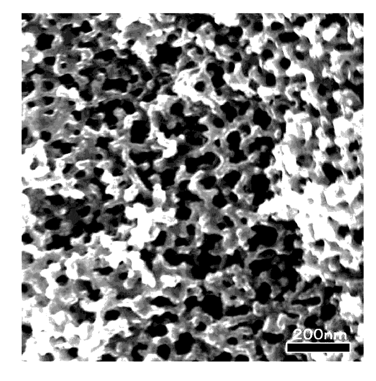
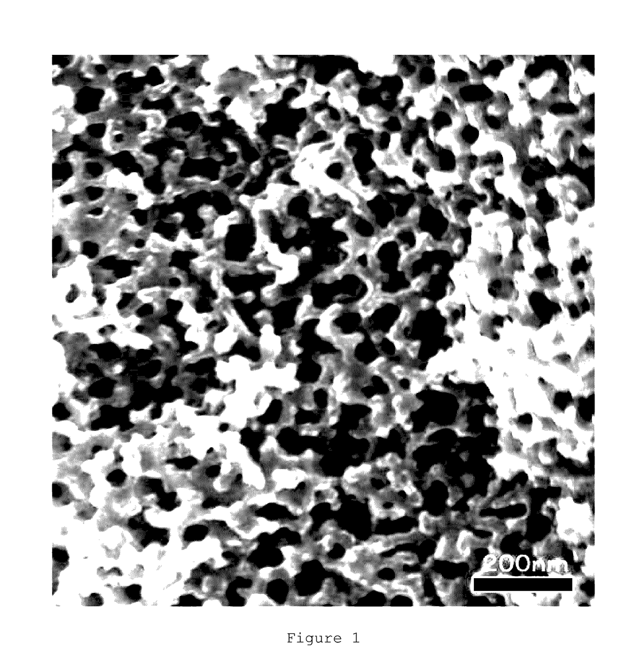
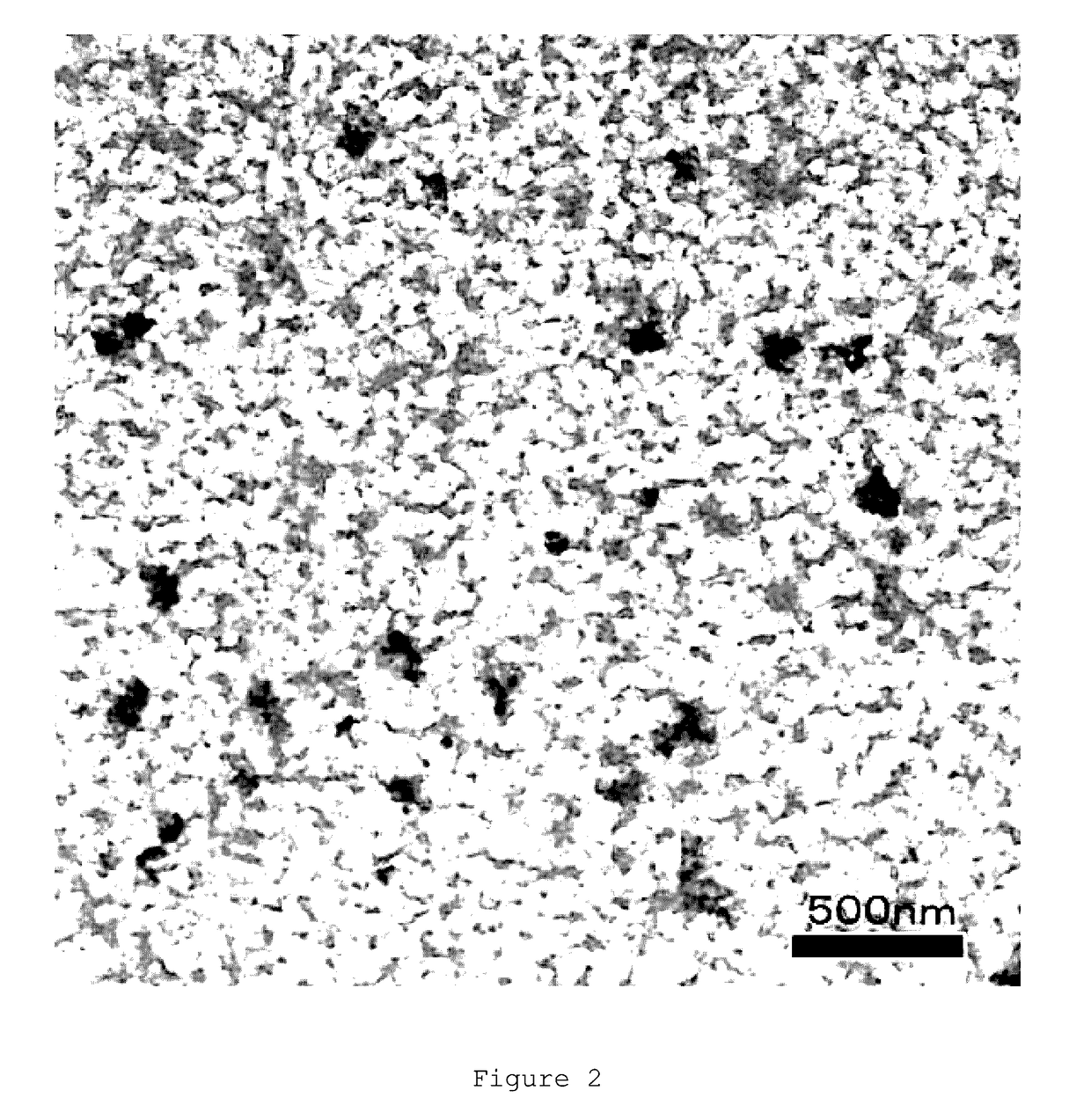
The present invention provides a porous carbon material with excellent electrical conductivity, thermal conductivity, pressure resistance, and strength against tension or compression. The material has a continuous porous structure composed of pores and branches, which allows for various functions such as filling and / or passing a fluid into or through the pores. Additionally, the material has some degree of resistance to deformations due to its continuous structure and contains carbon crystal grains, further improving its electrical conductivity, thermal conductivity, and mechanical property, making it applicable to various applications such as electric and electronic materials, or materials which mediate heat exchange, including heat dissipation materials.

Problems solved by technology

However, the carbonizable material and the eliminable material are a combination which forms a non-compatible system, and the mere addition of a compatibilizing agent cannot form continuous pores in the carbon fibers.
However, these carbon materials merely have a continuous porous structure introduced thereinto and have not had sufficient electrical conductivity, thermal conductivity, or strength.

Method used


Image

  • Porous carbon material
  • Porous carbon material
  • Porous carbon material

Examples


example 1

[0142]Into a separable flask were introduced 70 g of polyacrylonitrile (Mw, 150,000) manufactured by Polysciences, Inc., 70 g of polyvinylpyrrolidone (Mw, 40,000) manufactured by Sigma Aldrich, and 400 g of dimethyl sulfoxide (DMSO) manufactured by Wakenyaku Co. Ltd., as a solvent. The contents were heated at 150° C. for 3 hours with stirring and refluxing, thereby preparing an even and transparent solution. In this solution, the concentration of the polyacrylonitrile and the concentration of the polyvinylpyrrolidone were 13% by weight each.

[0143]The DMSO solution obtained was cooled to 25° C. and then ejected at a rate of 3 mL / min from a one-orifice nozzle having an orifice diameter of 0.6 mm, and the extrudate was led into a pure-water coagulating bath kept at 25° C., subsequently taken off at a rate of 6 m / min, and accumulated in a vat to thereby obtain raw fibers. In this operation, the air gap was set at 5 mm, and the length of immersion in the coagulating bath was 15 cm. The r...

example 2

[0150]Porous carbon fibers were obtained in the same manner as in Example 1, except that the carbonization temperature was 2000° C. and the atmosphere was changed from nitrogen to argon at a temperature of not less than 1500° C. The results are shown in Table 1.

example 3

[0151]Porous carbon fibers were obtained in the same manner as in Example 1, except that the carbonization temperature was 2500° C. and the atmosphere was changed from nitrogen to argon at a temperature of not less than 1500° C. The results are shown in Table 1.


PUM


Abstract

Provided is a porous carbon material which has excellent electrical conductivity, thermal conductivity, pressure resistance, and strength against tension and compression. This porous carbon material at least partially includes a continuous porous structure, and exhibits excellent electrical conductivity, thermal conductivity, pressure resistance, and strength against tension and compression by containing carbon crystal grains therein.

Description

CROSS REFERENCE TO RELATED APPLICATIONS[0001]This is the U.S. National Phase application of PCT International Application No. PCT / JP2015 / 067323, filed Jun. 16, 2015, and claims priority to Japanese Patent Application No. 2014-127884, filed Jun. 23, 2014, the disclosures of each of these applications being incorporated herein by reference in their entireties for all purposes.FIELD OF THE INVENTION[0002]The present invention relates to a porous carbon material which can be spread for various applications.BACKGROUND OF THE INVENTION[0003]As porous carbon materials, activated carbons having both macropores which are relatively large pores and micropores, such as particulate activated carbons and activated-carbon fibers; and fine carbons represented by carbon nanotubes and meso-porous carbons produced from meso-porous silica or zeolite template, are known.[0004]Patent Document 1 describes a technique for obtaining porous carbon fibers by mixing a carbonizable material with an eliminable ...

Claims


Application Information

Patent Timeline
IPC IPC(8): D01F9/12
CPCC01B31/02C01P2002/70C01P2006/40C01B32/05C01P2002/72C01P2004/61C01P2004/62C01P2004/64C01P2006/12C01P2006/32
Inventor MIHARA, TAKAAKITANAKA, KENTAROTAKEUCHI, KOSAKUHORIGUCHI, TOMOYUKI
Owner TORAY IND INC
Learn More