Moving system

Active Publication Date: 2017-05-18
SCHLUMBERGER TECH CORP
View PDF2 Cites 2 Cited by
  • Summary
  • Abstract
  • Description
  • Claims
  • Application Information

AI Technical Summary

Benefits of technology

[0008]In one aspect, embodiments of the present disclosure relate to methods, systems, and/or tools for the location of tools and/or features in a well using tube waves, which are also referred to herein as pressure waves, reflected from a tube wave reflector in the well, receiving a reflection of the tube wave from the reflector, e.g., with the receiver in a fixed location and or the tube wave generator at either a fixed absolute location or a fixed location relative to the reflector, and determining the dep

Problems solved by technology

It is commonly known the fluid flow through perforations into a formation during a fracturing operation is not uniform.
It is also well known that the resulting production is likewise extremely non-uniform, with a small fraction of the perforations producing the bulk of the production from the well.
However, a large number of wells already exist with poor distribution, and it may not be economically feasible to “refracture” such wells in a uniform manner.
This system is limited by the time required to get good quality data, the effect of the conveyance means on the well, and the resolution of the number of positions where data is collected.
However, this means that at least part of the well has to be taken

Method used


Image

  • Moving system
  • Moving system
  • Moving system

Examples


embodiments listing

[0166]In some aspects, the disclosure herein relates generally to well re-stimulation methods and / or workflow processes according to the following Embodiments, among others:

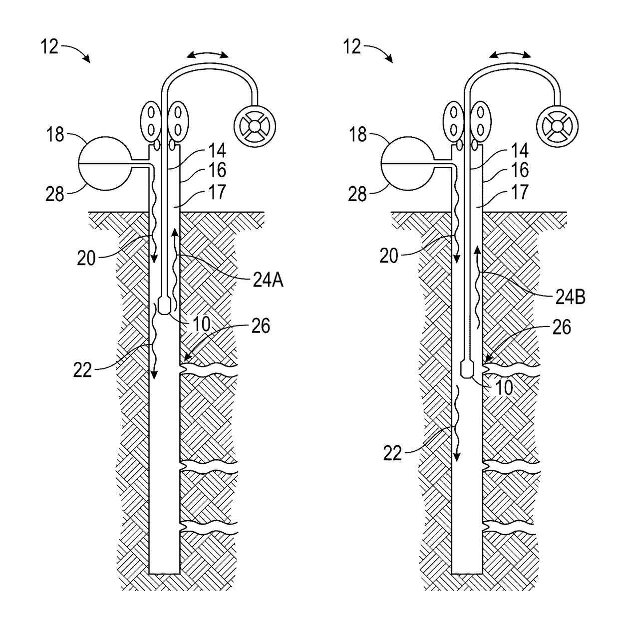
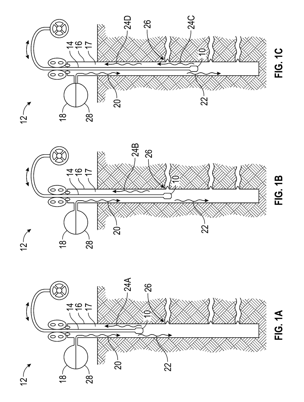
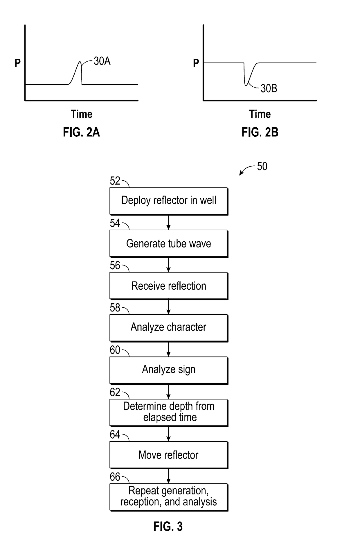
[0167]Embodiment 1: A method, comprising: (a) deploying a moveable tube wave reflector to a first location in the well; (b) generating a tube wave in the well; (c) receiving a reflection of the tube wave from the reflector; (d) determining the depth of the reflector based on the time between the tube wave generation and receipt of the reflection; (e) moving the reflector to a second location in the well; and (f) after moving the reflector, repeating the tube wave generation (b), the reflection receipt (c), and the determination of the depth of the reflector (d).

[0168]Embodiment 2: The method of Embodiment 1, wherein the reflector comprises an interface between fluids of contrasting tube wave velocity.

[0169]Embodiment 3: The method of Embodiment 1 or Embodiment 2, wherein the reflector comprises a reflective tool....

examples

[0197]The progress of pulses originating from the coiled tubing generator 108 of FIG. 6 and traveling down the coiled tubing 102 are shown in the ray-tracing chart 150 seen in FIG. 7 where origin 152 is time t=0. When the pulse 154 reaches the end of the coiled tubing 102 at the depth of the BHA 104 at time 156, three waves 158, 160, 162 are produced. Wave 158 goes downhole and reflects off the down hole reference (DHR) 164 at time 166. Wave 160 goes up the annulus 112, and at time 168 reaches transducer 120 located on the wellhead, and wave 162 goes up the coiled tubing 102 and reaches the circulating pressure transducer 118 at the swivel at time 170.

[0198]The reflection 172 from the DHR 164 is further split at time 174 when it encounters the BHA 104; wave 176 in the annulus 112 reaches the wellhead sensor 120 at time 178; and wave 180 in the coiled tubing 102 reaches the circulating pressure transducer 118 at time 182.

[0199]The relative speed of propagation of the tube waves in th...


PUM


Abstract

A method moves a tube wave reflector in a well, generates a tube wave, receives a reflection, and determines the depth of one or more reflector locations from the elapsed time. Also, a method to locate a feature in a well deploys a bottom hole assembly (BHA), generates acoustic noise from the BHA, and autocorrelates to determine the BHA depth. Also, a system has a coiled tubing string to a BHA, a surface wave generator, a surface and/or distributed receiver, and a recorder to determine elapsed times between generation and receipt.

Description

CROSS REFERENCE TO RELATED APPLICATION(S)[0001]None.BACKGROUND[0002]It is commonly known the fluid flow through perforations into a formation during a fracturing operation is not uniform. It is also well known that the resulting production is likewise extremely non-uniform, with a small fraction of the perforations producing the bulk of the production from the well. Efforts are ongoing to use targeted fracturing techniques to improve this situation by limiting the entry of fracturing fluid to specific locations in the well. However, a large number of wells already exist with poor distribution, and it may not be economically feasible to “refracture” such wells in a uniform manner.[0003]Existing methods to measure the non-uniformity of production, and determine the distribution or map of relative producibility, include downhole flow measurement devices that can be positioned and used at multiple locations in the well, and straddle packer systems to produce a from a specific area. Flow...

Claims


Application Information

Patent Timeline
IPC IPC(8): E21B47/09E21B17/20
CPCE21B47/091E21B17/20E21B34/06E21B33/12E21B43/26G01V1/52E21B47/095
Inventor SHAMPINE, ROD WILLIAMBOGDAN, ANDREYKEILERS, ADAMLECERF, BRUNO
Owner SCHLUMBERGER TECH CORP
Why Eureka
Try Eureka