Heat-dissipating component and method for manufacturing same

Active Publication Date: 2017-05-18
DENKA CO LTD
View PDF5 Cites 0 Cited by
  • Summary
  • Abstract
  • Description
  • Claims
  • Application Information

AI Technical Summary

Benefits of technology

The present invention provides a heat-dissipating component and a manufacturing method that can prevent damage (such as cracks and breakage) when affixing it to other components and during actual use. Additionally, it can also suppress shrinkage cavities and hole cavities during manufacture. This is achieved by addressing the defect of micro-cracks existing in the through holes and periphery of the component. Overall, the invention improves the reliability and durability of the heat-dissipating component.

Problems solved by technology

When trying to screw in aluminum silicon carbide composites having through holes formed by conventional methods in components such as heat-dissipating fins, there has been the problem of the periphery of the through holes cracking.
Further, even if there are no problems at the time of attachment, when the heat cycles are applied at the time of implementation, there has been the problem of cracks appearing in the hole portions.
In addition, there was a problem that defects occur in appearance due to occurrence of shrinkage cavities and hole cavities during impregnation with metal.
The present inventors, after seriously considering the cause and means to prevent the occurrence of cracks and breakage in through holes and the periphery thereof, discovered that the cause of the occurrence of cracks and breakage lies in the defect of micro-cracks existing in the through holes and periphery thereof and that, while aluminum silicon carbide composites have high strength, they have insufficient toughness, which leads to destruction.

Method used


Image

  • Heat-dissipating component and method for manufacturing same
  • Heat-dissipating component and method for manufacturing same
  • Heat-dissipating component and method for manufacturing same

Examples


examples

[0060]The present invention will be further explained with the following examples and comparative examples, though the present invention is not limited to these.

examples 1-6

[0061]Silicon carbide powder A (NG-150, average particle size 100 μM: manufactured by Pacific Rundum Co., Ltd.), silicon carbide powder B (GC-1000 F, average particle size 10 μm: manufactured by Yakushima Denko Co., Ltd.), and a silica sol (Snowtex: manufactured by Nissan Chemical Industries Co., Ltd.,) were blended in a composition at a mass ratio of 60:40:10 and mixed for one hour with a stirring mixer.

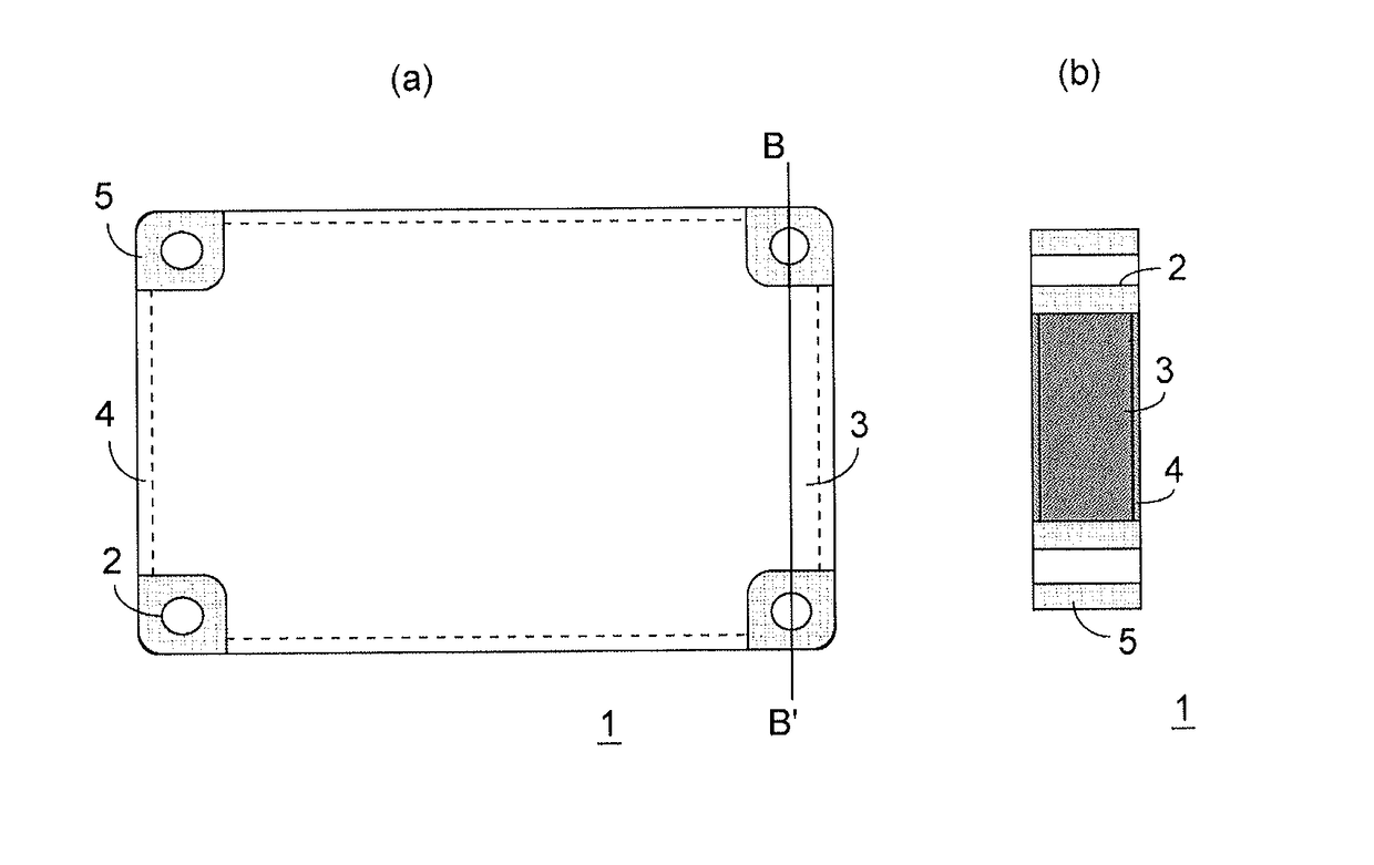
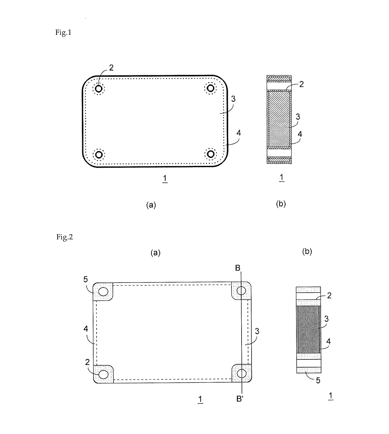
[0062]This mixed powder was molded, at a pressure of 10 MPa, into a shape of 120 mm×70 mm×7 mm having notches at the four corners. The four corners of the edges of this molded body had notches of 15 mm×15 mm. This molded body was dried for two hours at 120 degrees Celsius, and was heated for two hours at 960 degrees Celsius in air, leading to the manufacturing of a silicon carbide porous body.

[0063]Further, the obtained silicon carbide porous body was processed to a shape of 20 mmφ×7 mm, and the relative density as calculated from its dimensions and mass was 65%.

[0064]Next, the obta...

examples 7-12

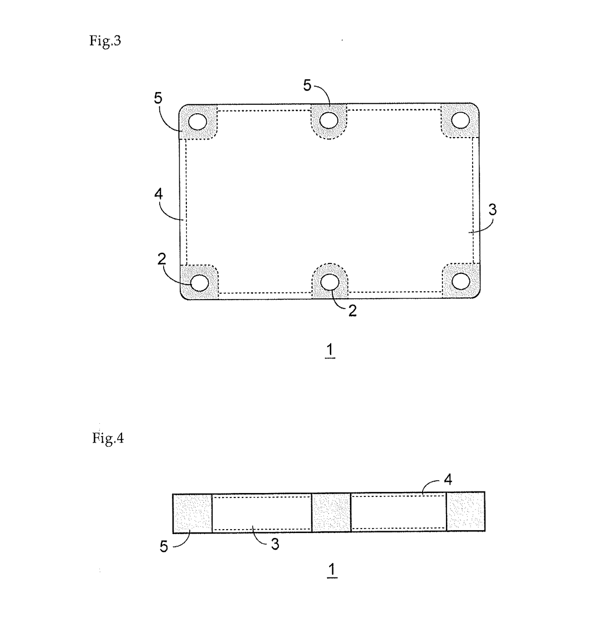
[0075]These examples were the same as example 1 with respect to the basic manufacturing method, except that the aluminum alloys comprised 0.1, 1, 5, 8, 16, and 18 mass % of silicon and 1.5, 1.2, and 0.1 mass % of magnesium, respectively, and the relative densities of the silicon carbide porous bodies were respectively 55, 65, and 75%. As the molded body, a molded body such as that illustrated in FIG. 3 was mold compressed to have U-shaped notch portions at the four corners and the long-side portions of the rectangular-shaped body, and in these portions, through holes having a diameter of 7.5 mm were formed. The size of the molded body was 130 mm×80 mm×5 mm, and the center position of the through holes was a position 7 mm inward from the outer peripheral surface. The U-shaped notch portions had a depth of 12 mm and a width of 10 mm. The distance between the centers of adjacent through holes on the same long side was 45 mm. For these heat-dissipating components, the same evaluation as...


PUM

PropertyMeasurementUnit
Fractionaaaaaaaaaa
Fractionaaaaaaaaaa
Percent by massaaaaaaaaaa

Abstract

A heat-dissipating component, and a method for manufacturing the same, the component provided with a composited portion including a plate-shaped molded body containing silicon carbide, and hole-formation portions formed in a peripheral edge portion of the composited portion; through-holes being formed in the hole formation sections; the hole-formation portions containing inorganic fibers; the molded body and the inorganic fibers being impregnated with an aluminum-containing metal; and the hole-formation portions forming a part of the outer peripheral surface of the heat-dissipating component.

Description

[0001]The present invention relates to a heat-dissipating component and a method for manufacturing the same.BACKGROUND ART[0002]In recent years, as heat-dissipating plates for power modules used in electric vehicles and electric railroad applications, aluminum silicon carbide composites are used in place of the conventional copper. While the thermal conductivity of aluminum silicon carbide composites is not as good as the thermal conductivity of copper, the thermal expansion coefficient thereof is 6-8 ppm / K, almost half of that of copper, which is 17 ppm / K, so the occurrence of cracking at the solder layer portion adhering the ceramic circuit board and the heat-dissipating plate that form the module is suppressed, and it is possible to obtain high reliability.[0003]Aluminum silicon carbide composites are manufactured, for example, as described in Patent Document 1, by mixing additives into a silicon carbide powder, after which, a molded body is formed by a dry press method, an extru...

Claims


Application Information

Patent Timeline
IPC IPC(8): H05K7/20C22C21/02C09K5/14B22D19/14C04B41/51C04B41/00C22C21/08B22D21/00
CPCH05K7/209C22C21/08C22C21/02C09K5/14B22D19/14C04B41/5155C04B41/009B22D21/007B22D19/00H01L23/3733H01L23/4006H01L21/4871C04B35/565Y10T428/12361C22C47/06C22C49/06C22C47/08C22C47/12C22C49/14
Inventor MIYAKAWA, TAKESHIKINO, MOTONORI
Owner DENKA CO LTD
Why Eureka
Try Eureka