Multi-electrode, Energy-Recycling, Resonant Stimulation Circuits and Architectures for Nerve Blocking

a nerve blocker and energy-recycling technology, applied in the field of multi-electrode, energy-recycling, resonant stimulation circuits and architectures for nerve blockers, can solve the problems of low energy benefit, low energy efficiency of power-supply techniques, and high energy consumption of current so as to reduce energy and power consumption of nerve blocker stimulation systems, energy-efficient and selective

Active Publication Date: 2017-05-25
RAHNIX INC
View PDF1 Cites 9 Cited by
  • Summary
  • Abstract
  • Description
  • Claims
  • Application Information

AI Technical Summary

Benefits of technology

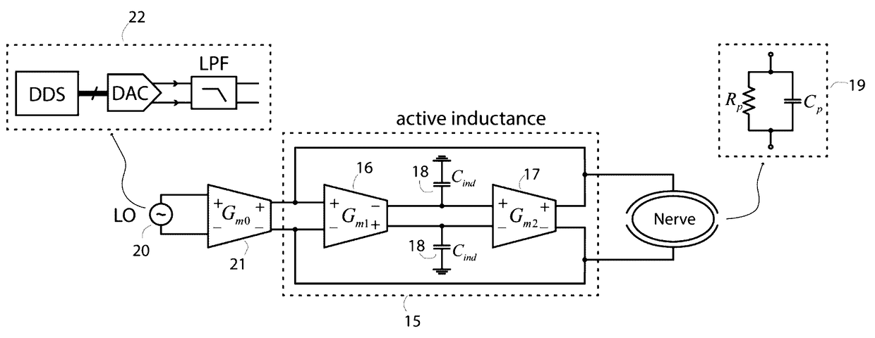
[0007]In this application, we disclose circuits and architectures for reducing energy and power consumption of nerve-blocking stimulation systems. These embodiments include but are not limited to i) the use of passive inductive, active inductive, active transconductor-capacitor, or piezoelectric strategies that serve to resonantly amplify and/or recycle capacitive nerve energy such that the nerve itself becomes an integral part of the circuit that creates its oscillatory blocking waveform; ii) mechanical multi-electrode configurations and stimulation paradigms that help increase the probability that most of the stim

Problems solved by technology

In fact, the energy consumption of current stimulation systems for nerve blocking is very high compared with those of even the most power-hungry FDA-approved stimulators for nerve excitation.
However, in blocking nerve stimulators, electrode impedances are typically not dominant such that it is the nerve impedance energy itself that need

Method used


Image

  • Multi-electrode, Energy-Recycling, Resonant Stimulation Circuits and Architectures for Nerve Blocking
  • Multi-electrode, Energy-Recycling, Resonant Stimulation Circuits and Architectures for Nerve Blocking
  • Multi-electrode, Energy-Recycling, Resonant Stimulation Circuits and Architectures for Nerve Blocking

Examples


Embodiment Construction

The Bridge-Cuff Blocking Stimulator

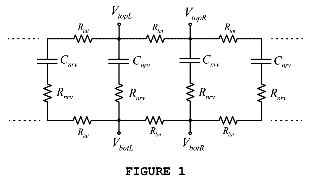
[0029]The ‘bridge cuff blocking stimulator’, which represents one embodiment of our invention, has two partially circumferential electrodes above the nerve, separated from each other by a small lateral distance as in current blocking stimulators. In addition, it has two partially circumferential electrodes below the nerve in symmetric locations, also separated from each other by the same lateral distance. Unlike a current blocking stimulator, we ensure that the lateral voltage drop across neighboring electrodes either below or above the nerve is always small. Thus, the lateral impedance of approximately 50Ω (estimated from 5V / 100 mA measurements in traditional blocking stimulators) always develops little voltage across it and does not dissipate power by design. A feedback loop in a current-stimulation strategy can enforce this adiabatic voltage constraint across two electrodes through various means. In a voltage-stimulation strategy, two electrode ...


PUM


Abstract

We disclose multi-electrode, energy-recycling, resonant stimulation circuits and strategies for energy-efficient blocking of action potentials in nerve. Our schemes increase the probability that most of the electrical stimulation is directed through the nerve rather than dissipated in ohmic extracellular solution alongside it via mechanical and electrical means; they use energy-recycling and resonant-amplification strategies that recycle and amplify capacitive nerve energy such that the nerve itself becomes an integral part of the circuit creating its oscillatory blocking waveform; they use traveling-wave strategies with distributed multi-electrode stimulation that alters the timing and intensity of stimulation at various points along the nerve to synchronize blocking stimulation with wave propagation in the nerve in an energy-efficient fashion. The schemes operate synergistically in a medical device to create advanced energy-efficient nerve-blocking stimulators whose operation may be altered and adapted in a feedback fashion to sensed action potentials in the nerve.

Description

CROSS REFERENCE TO RELATED APPLICATIONS[0001]This application claims benefit under 35 USC §119(e) of U.S. Provisional Patent Application Ser. No. 62 / 085,826 filed on Nov. 29, 2014, the contents of which are incorporated herein in their entirety by reference.STATEMENT REGARDING FEDERALLY SPONSORED RESEARCH OR DEVELOPMENT[0002]Not applicable.REFERENCE TO SEQUENCE LISTING, A TABLE, OR A COMPUTER PROGRAM LISTING COMPACT DISC APPENDIX[0003]Not applicable.BACKGROUND[0004]Action potential propagation can be blocked in nerves by alternating current excitation, as is described for example in J. Tanner, “Reversible Blocking of Nerve Conduction by Alternating Current Excitation”, NATURE, Vol. 195, pp. 718-719, Aug. 18, 1962. Typically, a relatively large pair of neighboring cuff electrodes circumferentially surround the nerve with a small lateral distance between them. A high-frequency a.c. waveform, usually in the 1 kHz to 100 kHz frequency range creates an oscillatory current or voltage wave...

Claims


Application Information

Patent Timeline
IPC IPC(8): A61N1/36A61N1/05
CPCA61N1/36125A61N1/36128A61N1/36071A61N1/0551
Inventor SARPESHKAR, RAHULWATTANAPANITCH, WORADORN
Owner RAHNIX INC
Why Eureka
Try Eureka