Fuel tank inerting prefilter assemblies, devices, and methods of use

a technology of inerting prefilters and fuel tanks, which is applied in the direction of machine/engine, auxillary pretreatment, separation processes, etc., can solve the problems of degrading affecting the performance of asm, and air, but mainly containing undesirable materials, and achieves low penetration air , high efficiency effect of particulate air

Active Publication Date: 2017-05-25
PALL CORP
View PDF0 Cites 22 Cited by
  • Summary
  • Abstract
  • Description
  • Claims
  • Application Information

AI Technical Summary

Problems solved by technology

This process air, however, typically contains undesirable material, including particulate contaminants, as well as water and oil aerosols.
This undesirable material can degrade the performance of the ASM.

Method used


Image

  • Fuel tank inerting prefilter assemblies, devices, and methods of use
  • Fuel tank inerting prefilter assemblies, devices, and methods of use
  • Fuel tank inerting prefilter assemblies, devices, and methods of use

Examples


Embodiment Construction

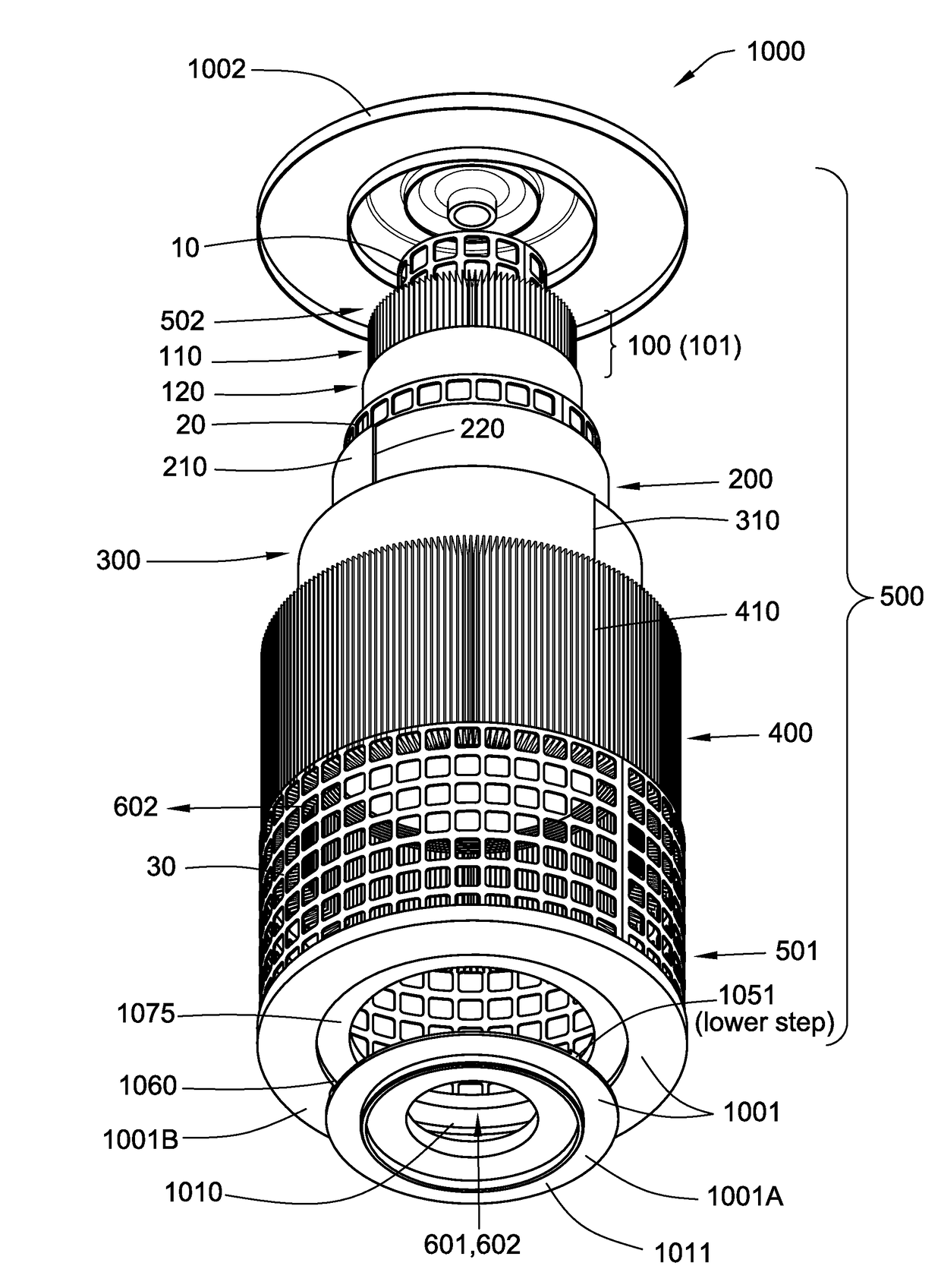
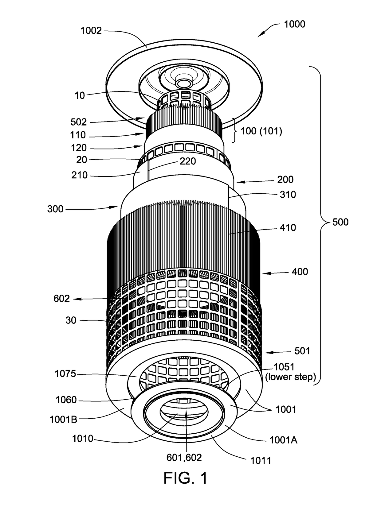
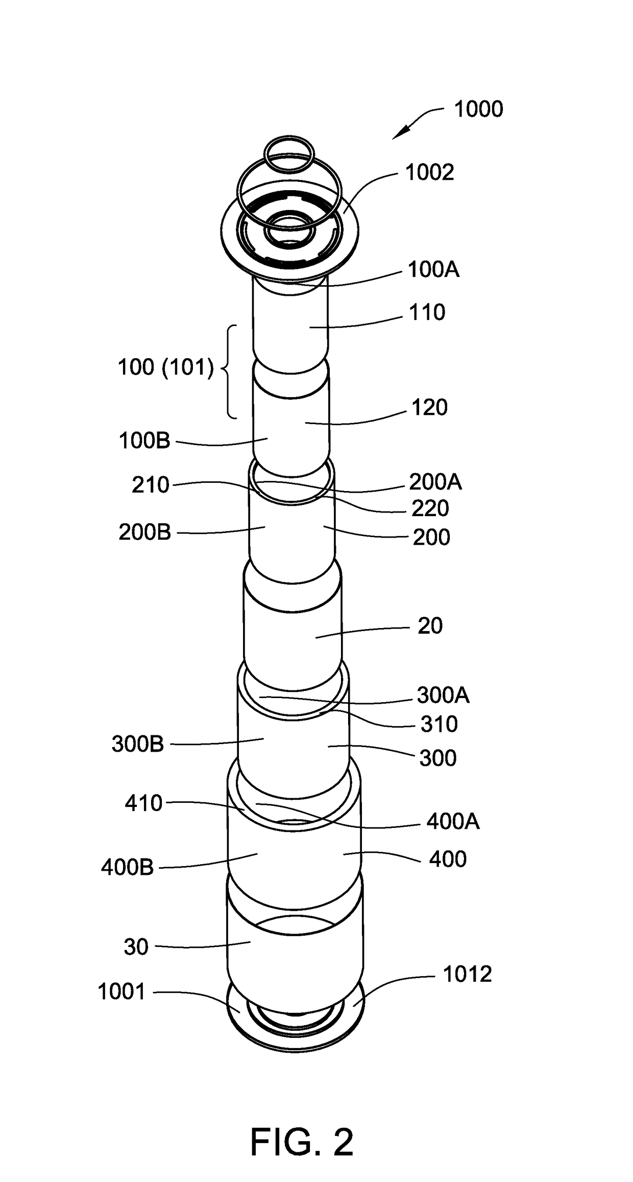
[0017]In accordance with an embodiment of the present invention, a fuel tank inerting prefilter assembly is provided comprising (a) a first endcap, wherein the first endcap includes a first side and a second side and a central opening passing from the first side through the second side; (b) a second endcap; (c) a first hollow cylindrical fluid treatment filter comprising a particulate removal and coalescer arrangement, the particulate removal and coalescer arrangement including a fibrous pleated porous medium having a pore size in the range from about 0.5 microns to about 50 microns; and an oleophobic and / or hydrophobic fibrous medium; (d) a second hollow cylindrical fluid treatment filter comprising an ozone depleting arrangement, the ozone depleting arrangement comprising an ozone depleting material (such as a deposited catalyst, for example, comprising manganese dioxide); (e) a third hollow cylindrical fluid treatment filter comprising an organic vapor depleting arrangement, the ...


PUM

PropertyMeasurementUnit
pore sizeaaaaaaaaaa
sizeaaaaaaaaaa
sizeaaaaaaaaaa

Abstract

Fuel tank inerting prefilter assemblies, fuel tank inerting prefilter devices, and methods for treating fluids, particularly process fluids used in fuel inerting tank systems, are disclosed.

Description

BACKGROUND OF THE INVENTION[0001]Flammability reduction systems, such as on-board inert gas generation systems (OBIGGS), nitrogen generation systems (NGS), flammability reduction systems (FRS), and fuel tank inerting systems (FTIS), are commonly used to reduce fuel tank combustion. In these systems, pressurized air from an engine, e.g., engine bleed air or process air, is passed through a membrane module, such as an air separation module (ASM), to separate oxygen from the process air, producing an oxygen-depleted inert gas such as primarily nitrogen-enriched air (NEA). The inert gas is introduced into the ullage (i.e., the space above the liquid fuel) in the fuel tank where it displaces the flammable fuel / air mixture to reduce the risk of an explosion or fire.[0002]This process air, however, typically contains undesirable material, including particulate contaminants, as well as water and oil aerosols. This undesirable material can degrade the performance of the ASM.[0003]However, wh...

Claims


Application Information

Patent Timeline
Patent Type & Authority Applications(United States)
IPC IPC(8): B01J19/14B01D46/00B01J15/00B01D53/04B01D51/10B01D46/52B01D46/54
CPCB01J19/14B60K2015/03236B01D46/0031B01D46/0036B01D46/543B01D53/04B01D51/10B01J15/005B01D2257/708B01D2257/106B01D2259/4566B01D2253/102B01D2253/108B01D2253/104B60K2015/03381B01D46/521B01D46/0012B01D46/525B01D53/8675F02M37/00F02M37/007B01D2255/2073B01D46/62B01D46/0027B01D46/2411B01D53/0431B01D2257/80B01D46/64
Inventor CARRION, ALEXANDERPATEL, RAJESH D.STEIN, DAVID JONATHAN
Owner PALL CORP
Why Eureka
Try Eureka