
Electrolysis device

a technology of electrolysis device and electrode, which is applied in the direction of electrolysis components, water treatment parameter control, chemistry apparatus and processes, etc., can solve the problems of reducing reducing the production amount per unit, and affecting the efficiency of electrolysis, so as to facilitate the electrode reaction and reduce the production cost. , the effect of efficient production

Inactive Publication Date: 2017-05-25
SHARP LIFE SCI CORP
View PDF3 Cites 1 Cited by
  • Summary
  • Abstract
  • Description
  • Claims
  • Application Information

AI Technical Summary

Benefits of technology

The present invention is an electrolysis device that efficiently produces electrolysis products. The device includes an electrolysis unit with a channel for fluid to be treated, electrolysis electrodes, and a flow inlet / outlet. The electrodes are positioned so that a fluid flows through an interelectrode channel, from lower to upper, allowing for efficient production of electrolysis products. The device also includes an inclined electrode pair and a channel that facilitates the flow of fluid, resulting in improved production efficiency of electrolysis products.

Problems solved by technology

However, when the concentration of an aqueous hypochlorite solution produced by electrolysis is low, the concentration of an organic material contained in water to be treated is sometimes increased, or an object to be disinfected to which a relatively large amount of an organic material adheres cannot be sometimes sufficiently disinfected.
However, a long hold time decreases the production amount per unit time, and use of multistage electrodes degrades the productivity and increases the cost.
Furthermore, when these methods are employed, a large amount of hydrogen gas is generated.
However, use of such an acidic aqueous hypochlorite solution tends to generate chlorine gas in addition to hydrogen gas.
In such a configuration, however, the flow velocity of an electrolysis solution around the center of an interelectrode channel is high, and the flow velocity of an electrolysis solution around the ends is low.
Therefore, the time for which the electrolysis solution is electrolyzed varies depending on the paths through which the electrolysis solution flows, which decreases the production efficiency of an electrolysis product.

Method used


Image

  • Electrolysis device
  • Electrolysis device
  • Electrolysis device

Examples


first embodiment

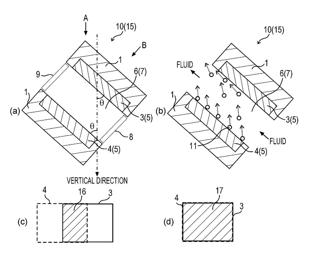
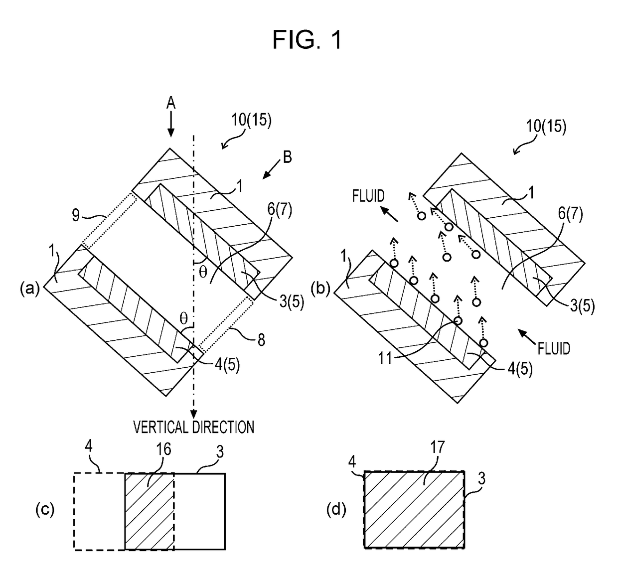
[0106]FIGS. 1(a) and 1(b) are schematic sectional views of an electrolysis device according to the first embodiment. FIG. 1(c) is a diagram for describing an overlap of an upper electrode and a lower electrode when the electrolysis device in FIG. 1(a) is viewed in a vertical direction A. FIG. 1(d) is a diagram for describing an overlap of an upper electrode and a lower electrode when the electrolysis device in FIG. 1(a) is viewed in a direction B perpendicular to a principal surface of the lower electrode.

[0107]An electrolysis device 15 according to the first embodiment includes an electrolysis unit 10. The electrolysis unit 10 includes a channel 7 for fluid to be treated, at least one electrolysis electrode pair 5, a flow inlet 8, and a flow outlet 9. The electrolysis electrode pair 5 is disposed so as to incline with respect to the vertical direction, includes an upper electrode 3 and a lower electrode 4 disposed so as to face each other, and is disposed so that an electrode react...

second embodiment

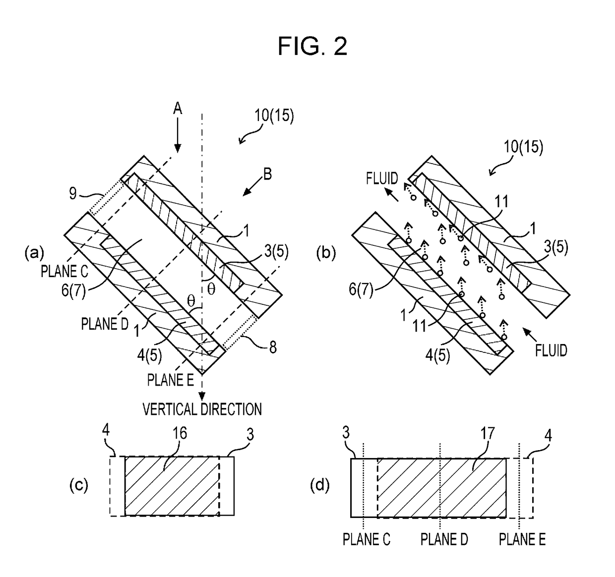
[0134]FIGS. 2(a) and 2(b) are schematic sectional views of an electrolysis device according to the second embodiment. FIG. 2(c) is a diagram for describing an overlap of an upper electrode and a lower electrode when the electrolysis device in FIG. 2(a) is viewed in a vertical direction A. FIG. 2(d) is a diagram for describing an overlap of an upper electrode and a lower electrode when the electrolysis device in FIG. 2(a) is viewed in a direction B perpendicular to a principal surface of the lower electrode.

[0135]In the electrolysis device in FIG. 1, the upper electrode 3 and the lower electrode 4 are disposed so that substantially the entire surfaces of the upper electrode 3 and the lower electrode 4 overlap each other when viewed in the direction B. However, in the electrolysis device 15 according to the second embodiment, the upper electrode 3 is disposed so as to shift upward. Specifically, as illustrated in FIG. 2(d), when viewed in the direction B perpendicular to the principal...

third embodiment

[0140]FIG. 3(a) is a schematic sectional view of an electrolysis device according to the third embodiment. FIG. 3(b) is a diagram for describing an overlap of an upper electrode and a lower electrode when the electrolysis device in FIG. 3(a) is viewed in a vertical direction A. FIG. 3(c) is a diagram for describing an overlap of an upper electrode and a lower electrode when the electrolysis device in FIG. 3(a) is viewed in a direction B perpendicular to an electrode surface of the lower electrode.

[0141]In the electrolysis devices 15 illustrated in FIGS. 1 and 2, the electrode surface of the upper electrode 3 and the electrode surface of the lower electrode 4 have substantially the same size. However, in the electrolysis device 15 according to the third embodiment, the electrode surface of the lower electrode 4 is larger than that of the upper electrode 3. Furthermore, as illustrated in FIG. 3(c), ower electrode 4 can be disposed so that when the electrolysis device 15 is viewed in t...


PUM

PropertyMeasurementUnit
inclination angleaaaaaaaaaa
forceaaaaaaaaaa

Abstract

An electrolysis device of the present invention includes an electrolysis unit. The electrolysis unit includes a channel for fluid to be treated, at least one electrolysis electrode pair, a flow inlet, and a flow outlet. The electrolysis electrode pair is disposed so as to incline with respect to a vertical direction and includes an upper electrode and a lower electrode disposed so as to face each other. The channel for fluid to be treated is disposed so that a fluid that has flowed in from the flow inlet flows through an interelectrode channel between the upper electrode and the lower electrode from a lower side to an upper side and flows out from the flow outlet.

Description

TECHNICAL FIELD[0001]The present invention relates to an electrolysis device and particularly to a diaphragmless electrolysis device.BACKGROUND ART[0002]Electrolysis is practically used for, for example, production of chemical materials. Basic chemical raw materials such as sodium hydroxide (caustic soda), chlorine gas, hydrogen gas, and sodium carbonate (soda ash) are produced by, for example, an electrolytic soda process. In addition to industrial uses, an electrolysis technique is also used for home appliances such as an alkaline ionized water filter.[0003]The advantage of such an electrolysis technique is that an active substance can be produced from a harmless material having almost no activity. For example, hypochlorites such as sodium hypochlorite is used as a bleaching agent and a germicide for treating clean and sewage water, for treating a drain, and for household kitchens and washing. Hypochlorites are produced by a method in which an alkali hydroxide obtained by electrol...

Claims


Application Information

Patent Timeline
Patent Type & Authority Applications(United States)
IPC IPC(8): C25B1/34C25B15/08C25B9/00
CPCC25B1/34C25B15/08C25B9/00C02F1/46104C02F1/4618C02F1/4674C25B1/26C02F2001/46142C02F2001/46185C02F2201/4611C02F2209/29C02F2301/024C25B9/17
Inventor ARAI, NOBUTOSHISAKAMOTO, YASUHIROHAYASHI, NOBUHIRO
Owner SHARP LIFE SCI CORP
Learn More