Fin - shaped - plate (FSP) egr cooler

a technology of heat exchanger and egr, which is applied in the direction of machines/engines, laminated elements, lighting and heating apparatus, etc., can solve the problems of negative impact on the cylinder filling and thus on the power density of the engine, and reducing the cooling effect of the combustion exhaust gas recirculation, etc., to achieve the effect of low cost, low cost of cost-intensive solder paste, and high precision

Inactive Publication Date: 2017-06-01
HANON SYST
View PDF10 Cites 6 Cited by
  • Summary
  • Abstract
  • Description
  • Claims
  • Application Information

AI Technical Summary

Benefits of technology

[0026]In order to ensure a large-area connection of the rib or the rib element with the wall element or the tube wall, on the one hand a high precision with extremely slight tolerances of the dimensions of the ribs, especially the rib height, as well as the wall elements is absolutely essential. On the other hand, a great deal of solder is used in the fabrication of the known heat exchanger, which causes high costs for cost-intensive solder paste. Furthermore, the soldering process must ensure a good connection of the elements, and a poor connection reduces the stability and the risk of a crack will increase.

Problems solved by technology

During combustion at high temperatures, environmentally harmful nitrogen oxides are produced in the engine of motor vehicles, especially when using lean fuel mixtures, that is, in the partial load range.
However, the mixing in of the recirculated exhaust gas flow with high temperatures reduces the cooling effect of the exhaust gas recirculation on the combustion.
Furthermore, a mixture of air and exhaust with high temperatures that is aspirated by the engine has negative impact on the cylinder filling and thus on the power density of the engine.
However, increasingly strict legislation regarding exhaust gas standards and fuel consumption requirements for motor vehicles are making necessary an increased need for cooling with ever smaller footprint of the components in the motor vehicle.
These contrary requirements are seldom fulfilled by the known exhaust gas heat exchangers.
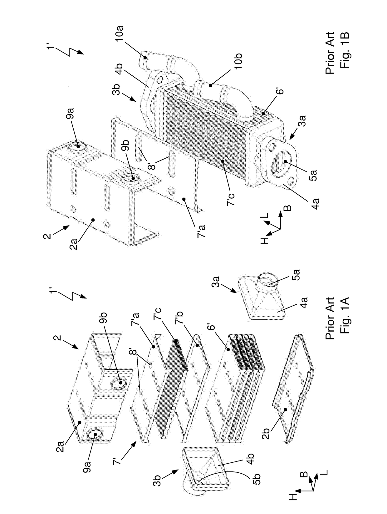
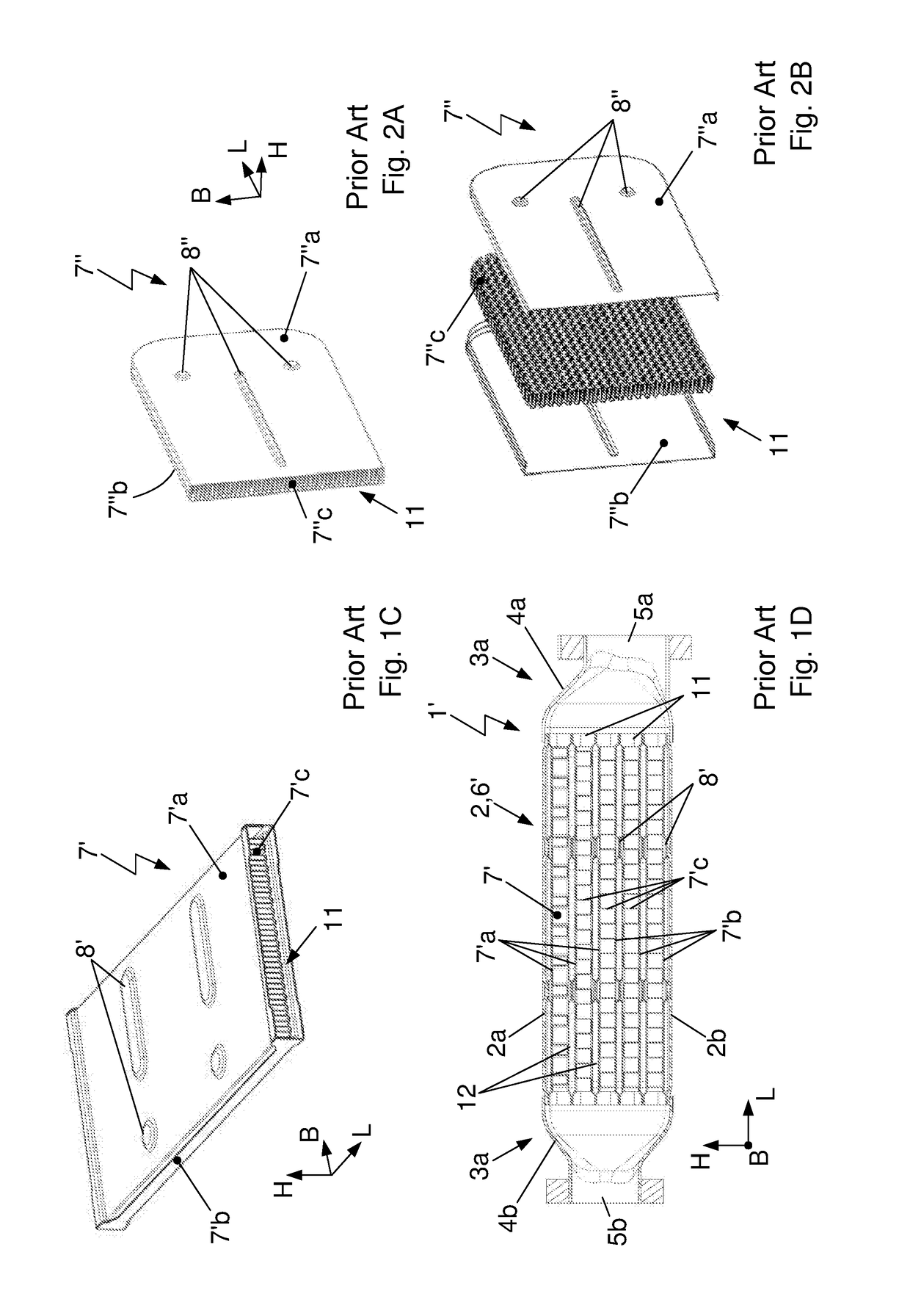
For the fabrication of the three elements, at least three different punching tools are required, which demands a high expenditure of material and causes high costs.
High-precision elements and their fabrication methods, which are needed for a soldering of the tube to the rib element, cause a high expense and high costs.
Furthermore, a guided conducting of the coolant through bulges 8″, as are especially evident in FIGS. 2A and 2B, is not possible, so that additional baffle plates must be installed for the guiding of the coolant.
Furthermore, the turbulence of the exhaust gas mass flow and thus the heat transfer from exhaust gas to the rib and to the coolant is also increased with corrugated ribs in the case of gasoline engines.
If the rib or the rib element is not soldered to the wall element or the tube wall, a gap will form which is filled with exhaust gas, having an insulating effect and thus substantially impairing the heat transfer.
Furthermore, the exhaust gas and / or the coolant is under high pressure, so that a large pressure difference is established between the inside and the outside of the tube wall.
On the other hand, a great deal of solder is used in the fabrication of the known heat exchanger, which causes high costs for cost-intensive solder paste.
Furthermore, the soldering process must ensure a good connection of the elements, and a poor connection reduces the stability and the risk of a crack will increase.

Method used


Image

  • Fin - shaped - plate (FSP) egr cooler
  • Fin - shaped - plate (FSP) egr cooler
  • Fin - shaped - plate (FSP) egr cooler

Examples


second embodiment

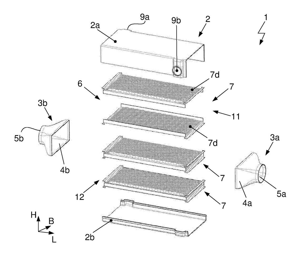
[0096]In the second embodiment, according to the second view of FIG. 6B as well as according to FIG. 7, the flow region 19 of the coolant has the shape of a parallelogram. The connection ports 10a, 10b for the coolant are arranged on oppositely situated first side walls 13 of the heat exchanger elements 7d or on oppositely situated long sides of the heat exchanger 1, similar to FIG. 5B.

third embodiment

[0097]In the third embodiment, according to the third view of FIG. 6C as well as FIGS. 8A and 8b, the flow region 19 of the coolant has the shape of a trapezium. The connection ports 10a, 10b for the coolant are arranged on a common first side wall 13 of the heat exchanger elements 7d or on a common long side of the heat exchanger 1. The extension of the first side walls 13 in the height direction H is adapted to the ribs 15 or to the rib contour. The shapes of the first side walls 13 here correspond to the respective adjacent ribs 15.

[0098]In both the second and the third embodiment, the flow cross section for the coolant becomes smaller in the inlet region 17 in the flow direction 16 of the coolant, while the flow cross section for the coolant becomes greater in the outlet region 18 in the flow direction 16 of the coolant and thus in the direction along the second side walls 14.

[0099]FIG. 9 shows a wall element 7d of a heat exchanger element 7 for a U-shaped exhaust gas flow duct ...


PUM


Abstract

A heat exchanger includes a heat exchanger housing with an exhaust gas inlet adapter and an exhaust gas outlet adapter, which encloses and bounds off a flow space for a coolant. The heat exchanger is furthermore configured with platelike heat exchanger elements arranged in parallel with each other and forming exhaust gas flow ducts, through which exhaust gas flows and around which liquid coolant flows. A heat exchanger element comprises two wall elements, which are joined together on opposite side surfaces and are configured with ribs on both surfaces. The ribs are arranged on an inner side and within the exhaust gas flow duct and on an outer side of the heat exchanger element. Adjacent heat exchanger elements arranged with outer sides facing each other are joined together at end faces abutting each other, forming a coolant flow duct having the ribs disposed therein.

Description

CROSS-REFERENCE TO RELATED APPLICATIONS[0001]This patent application claims priority under 35 U.S.C. §119 to German Patent Application No. 10 2015 120 591.2 filed on Nov. 27, 2015, and German Patent Application No. 10 2016 122 455.3 filed on Nov. 22, 2016, the disclosures of which are incorporated herein by reference in their entirety.TECHNICAL FIELD[0002]The invention concerns a heat exchanger for exhaust gas cooling in motor vehicles. The heat exchanger comprises a heat exchanger housing with an exhaust gas inlet adapter and an exhaust gas outlet adapter, which encloses and bounds off a flow space for a coolant and which comprises an inlet opening as well as an outlet opening for the coolant. The heat exchanger is furthermore configured with platelike heat exchanger elements arranged in parallel with each other and forming exhaust gas flow ducts, through which exhaust gas flows and around which liquid coolant flows.[0003]Furthermore, the invention concerns a method for the product...

Claims


Application Information

Patent Timeline
Patent Type & Authority Applications(United States)
IPC IPC(8): F02M26/32
CPCF02M26/32F01N3/02F28D9/00F28D2021/008F28F3/025F28F2275/06F01N3/0205F01N2240/02F28D9/0062F28F3/12F28F2255/08
Inventor OHREM, CARSTENGAUSS, MICHAELNOTHBAUM, JURGEN
Owner HANON SYST
Why Eureka
Try Eureka