

Coiled spring assembly
- Summary
- Abstract
- Description
- Claims
- Application Information
AI Technical Summary
Benefits of technology
Problems solved by technology
Method used
Image

Examples
embodiment 1
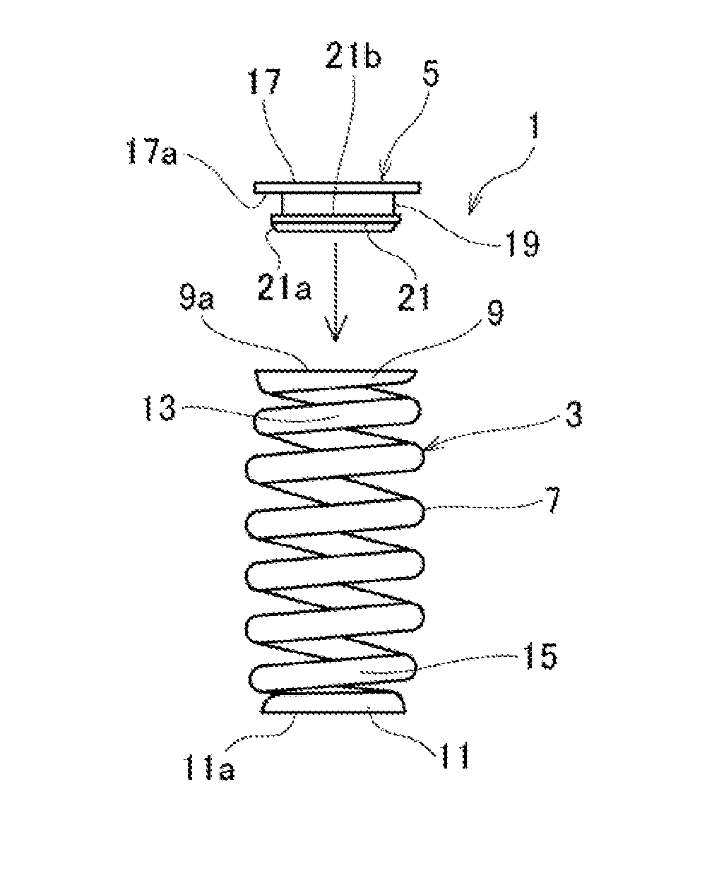
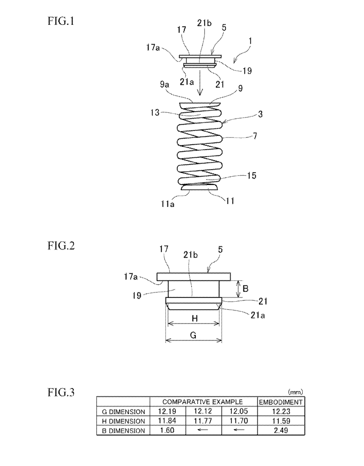
[0034]FIG. 1 is a side view illustrating a coiled spring and a seat for the coiled spring resolved from a coiled spring assembly according to the present invention.
[0035]The coiled spring assembly 1 of FIG. 1 is used as, for example, a transmission damper or a rebound spring for a chassis of a vehicle.
[0036]The coiled spring assembly 1 comprises a coiled spring 3 and a seat 5 for the coiled spring.
[0037]The coiled spring 3 is not limited in material, but is made of, for example, high strength material such as oil-tempered silicon-chromium spring steel wire (SWOSC), and is provided with end turns 9 and 11 formed at respective ends of a body portion 7 up to first turns with a relatively reduced diameter. Between the body portion 7 and the end turns 9 and 11, the coiled spring has transition portions 13 and 15 with a diameter gradually increasing from the end turns 9 and 11 to the body portion 7.
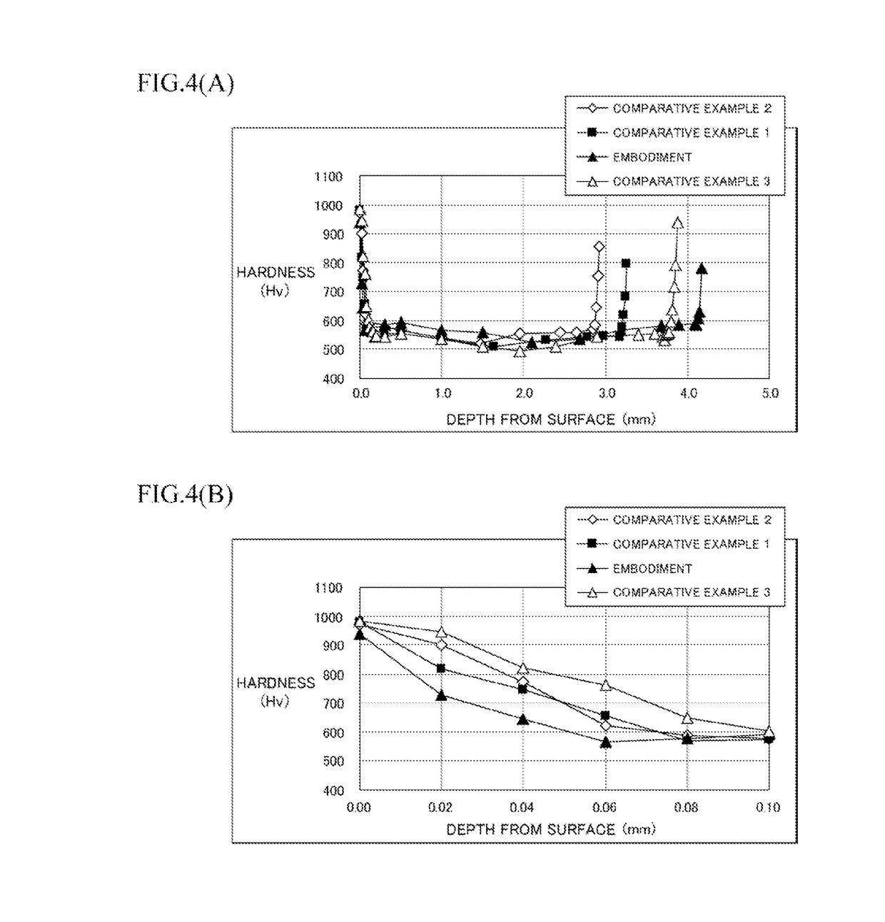
[0038]The coiled spring 3 has a surface layer of a depth being 50 μm and a white layer of a...
embodiment 2
[0084]FIGS. 10 and 11 pertain to attachment of seats for coiled springs of the embodiment 2 in which (A) are sectional views of essential parts and (B) are enlarged sectional views of a XB part and a XIB part of (A) of the essential parts.
[0085]As illustrated in FIGS. 10 and 11, in a coiled spring 3A of the embodiment of the present invention, an element wire with an oval cross-section is used instead of the element wire with the circular cross-section. In the coiled spring 3A, a cross-section of a coiled inner diameter side 3Aa of the element wire is formed by, for example, a semi-oval-shaped portion and a cross-section of a coiled outer diameter side 3Ab is formed by a semi-circular-shaped portion.
[0086]The example of FIG. 10 represents that a clearance between the end turn 9A (11A) and the enlarged diameter portion 21 of the seat 5 for the coiled spring is larger than that of the embodiment 1 if a curvature radius of the semi-circular-shaped portion of the coiled outer diameter s...
PUM
 Abstract
Description
Claims
Application Information