Magnetic detection device and method for manufacturing same

a magnetic detection and z-axis direction technology, applied in the field of magnetic detection, can solve the problems of incomparably high sensitivity, difficult to reduce the size and thickness of conventional three-dimensional magnetic detection devices, and achieve the effect of reducing the size of the magnetic detection devi

Active Publication Date: 2017-06-08
AICHI STEEL
View PDF7 Cites 17 Cited by
  • Summary
  • Abstract
  • Description
  • Claims
  • Application Information

AI Technical Summary

Benefits of technology

[0008]PTL 2 proposes a magnetic detection device in which, for example, a pair of MI elements for X-axis opposing each other and another pair of MI elements for Y-axis opposing each other are orthogonally arranged, a magnetic field direction changing body of a soft magnetic material is provided at the center of the MI elements, and a detection voltage obtained from each MI element is calculated thereby to obtain a magnetic component in the Z-axis direction. In this case, the MI element for Z-axis can be omitted and the magnetic detection device can thus be considerably reduced in size.

Problems solved by technology

In recent years, MI elements are focused on, which are entirely different in the structure and principle from such conventional elements and have incomparably high sensitivity.
Accordingly, the conventional three-dimensional magnetic detection device is difficult to be reduced in size and thickness in the Z-axis direction.

Method used


Image

  • Magnetic detection device and method for manufacturing same
  • Magnetic detection device and method for manufacturing same
  • Magnetic detection device and method for manufacturing same

Examples


first example

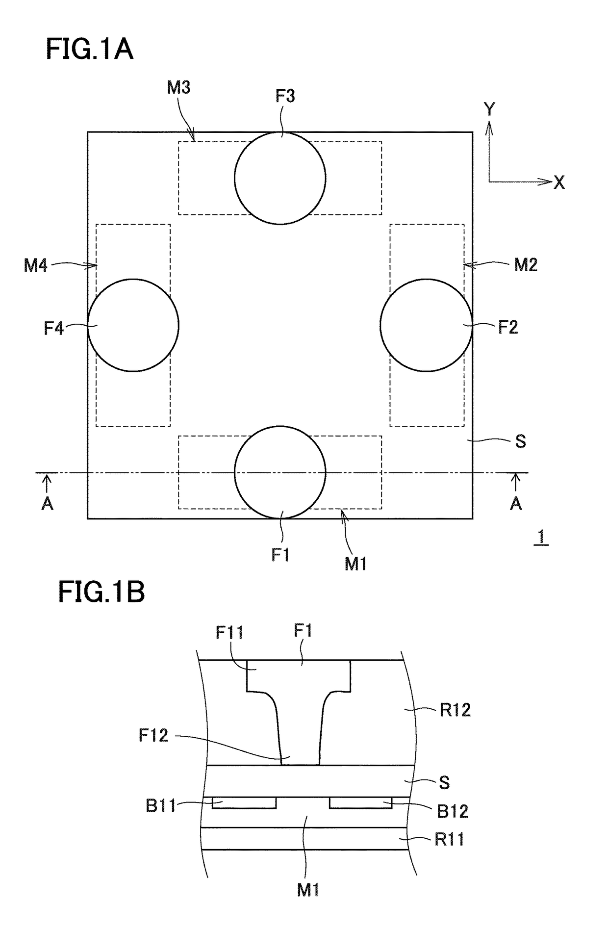
[0056]FIG. 1A is a plan view of an MI sensor 1 as an example according to the magnetic detection device of the present invention. FIG. 1B is a partial cross-sectional view along line A-A illustrated in FIG. 1A.

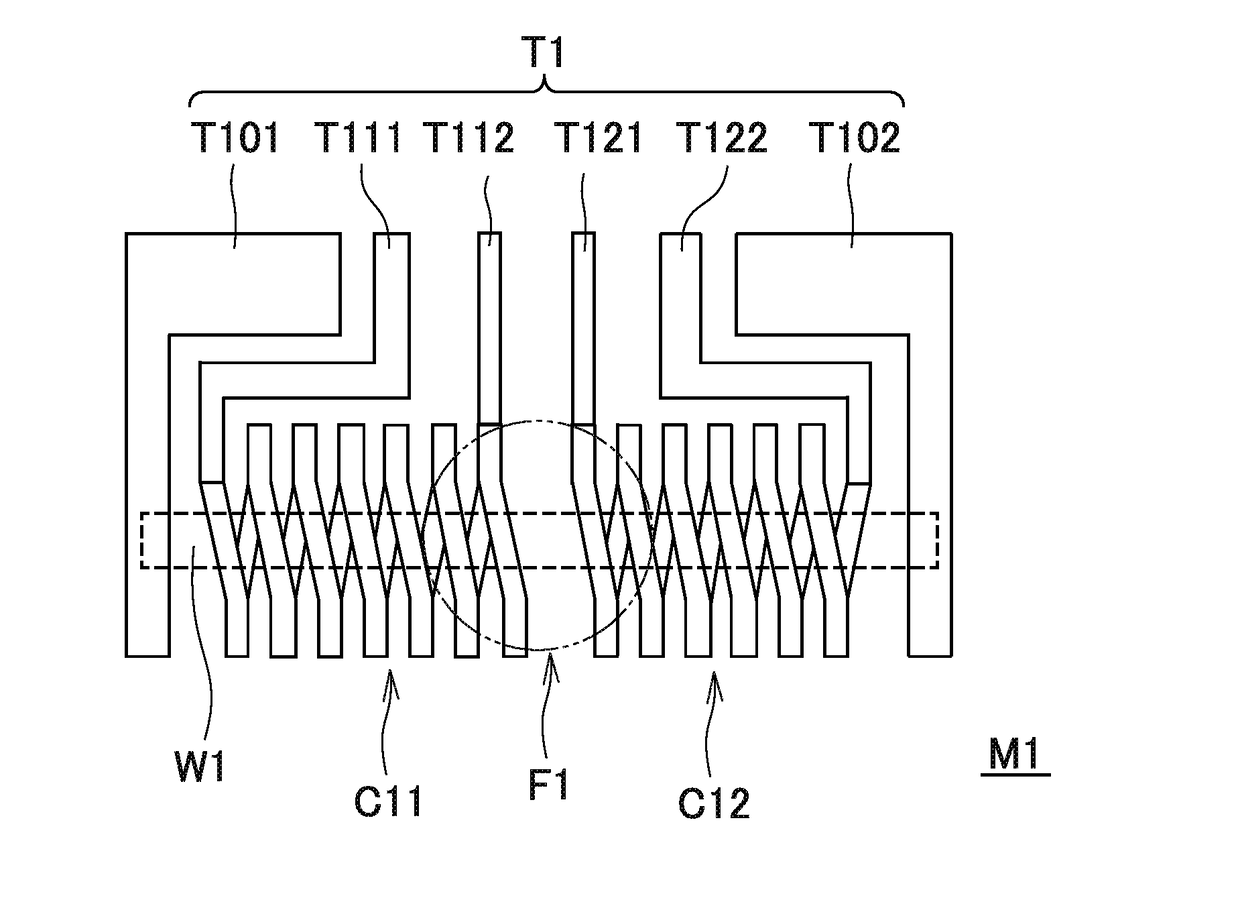
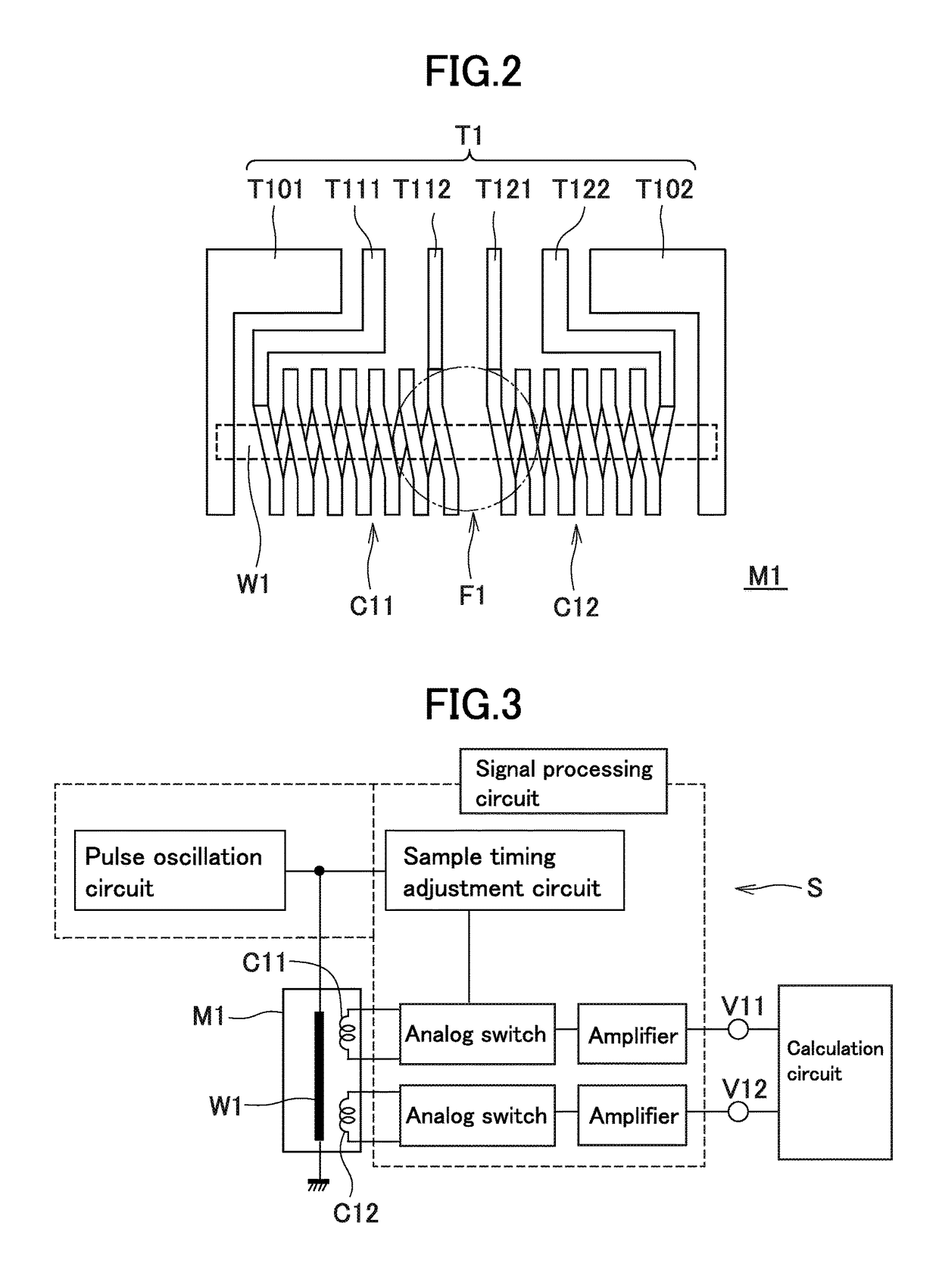
[0057]The MI sensor 1 has four MI elements M1 to M4 that detect an external magnetic field such as geomagnetism, four magnetism collecting yokes F1 to F4 (magnetic field direction changing bodies) each having a shape approximately of frustum of circular cone, a circuit substrate S (corresponding to the “substrate” as referred to in the present invention) configured such that an integrated circuit (ASIC: application specific integrated circuit) including a pulse oscillation circuit (drive circuit), a signal processing circuit, a calculation circuit, and other necessary circuits are formed on a Si substrate, and insulating resin layers R11 and R12 formed respectively on the upper surface and lower surface of the circuit substrate S. As illustrated in FIG. 1B, bumps B11 and B12 a...

second example

[0073]FIG. 9 illustrates an MI sensor 2 provided with a magnetism collecting yoke F1 of which the shape is modified from that of the magnetism collecting yoke F1 in the first example. Similar components to those in the first example are denoted by the same reference characters and the description thereof will be omitted. The same applies to other examples.

[0074]The magnetism collecting yoke FW of the MI sensor 2 has a cross-like shape and disposed on the center at the other surface side of a circuit substrate S. Extending parts FW1 to FW4 of the magnetism collecting yoke FW correspond to the center positions of MI elements M1 to M4, respectively, and the magnetism collecting yoke FW has an integral structure in which the extending parts FW1 to FW4 are connected at a center part FW0. The magnetism collecting yoke FW having such a symmetric shape can also perform similar functions to those of the magnetism collecting yoke F1 and other yokes.

[0075]The MI sensor 2 comprising the magneti...

third example

[0076]FIG. 10 illustrates an MI sensor 3 in which magnetism collecting yokes Fs are disposed in the vicinities of both ends at the side of MI element M1 of the circuit substrate S. Each of the magnetism collecting yokes Fs is reduced in size from the magnetism collecting yoke F1. By arranging the magnetism collecting yoke F1 (primary magnetic field direction changing body) and the magnetism collecting yokes Fs (subsidiary magnetic field direction changing bodies) in this manner, the convergence and direction change of the magnetic flux lines intersecting the circuit substrate S can be more easily controlled.


PUM


Abstract

A reduced size/thickness magnetic detection device includes: a substrate; and a magneto-impedance element at one substrate surface side and including a magneto-sensitive wire and a detection coil. The wire senses an external magnetic field component in a first axis direction in which the wire extends. The coil loops around the wire, and includes left-side and right-side coil parts coexisting along the wire, and a magnetic field direction changing body of soft magnetic material having at least a part at another substrate surface side or in the substrate above an intermediate position between left-side and right-side coil parts. The body can change an external magnetic field component in a third axis direction intersecting the substrate to a measurement magnetic field component in the first axis direction. The external magnetic field component in the third axis direction can be detected from a left-side coil part output and a right-side coil part output.

Description

TECHNICAL FIELD[0001]The present invention relates to a magnetic detection device (including a single body of an “MI sensor”) that detects magnetism using a magneto-impedance element (referred to as an “MI element”) and a method of manufacturing the same.BACKGROUND ART[0002]Magnetic measurement has conventionally been performed to know the orientation and the like. For example, electronic compasses and other similar devices measure a three-dimensional magnetic vector to know the accurate orientation. Measurement of the magnetic vector is performed by a magnetic sensor. Examples of such magnetic sensors include Hall elements and MR elements. In recent years, MI elements are focused on, which are entirely different in the structure and principle from such conventional elements and have incomparably high sensitivity.[0003]MI elements utilize a magneto-impedance effect (referred to as an “MI effect”) that, when a high frequency pulse current or the like is caused to flow through a magne...

Claims


Application Information

Patent Timeline
Patent Type & Authority Applications(United States)
IPC IPC(8): G01R33/06G01C17/30G01R33/00H01L43/12H01L27/22G01R33/02H01L43/02
CPCG01R33/063G01R33/0206G01C17/30G01R33/0052H01L43/12H01L27/22H01L43/02G01R33/028G01R33/0017G01R33/0023G01R33/02H10B61/00H10N59/00H10N50/00H10N50/01H10N50/80
Inventor YAMAMOTO, MICHIHARUNAGAO, TOMOHIKO
Owner AICHI STEEL
Why Eureka
Try Eureka