
Method for checking the function of a compression release brake system

a technology of compression release and function, which is applied in the direction of engine starters, electric control, machines/engines, etc., can solve the problems of poor possibility of engine braking, degrading the function of such a compression release brake system for different reasons, and deteriorating the braking effect, etc., to achieve convenient operation, short time, and low cost

Active Publication Date: 2017-06-22
SCANIA CV AB
View PDF3 Cites 12 Cited by
  • Summary
  • Abstract
  • Description
  • Claims
  • Application Information

AI Technical Summary

Benefits of technology

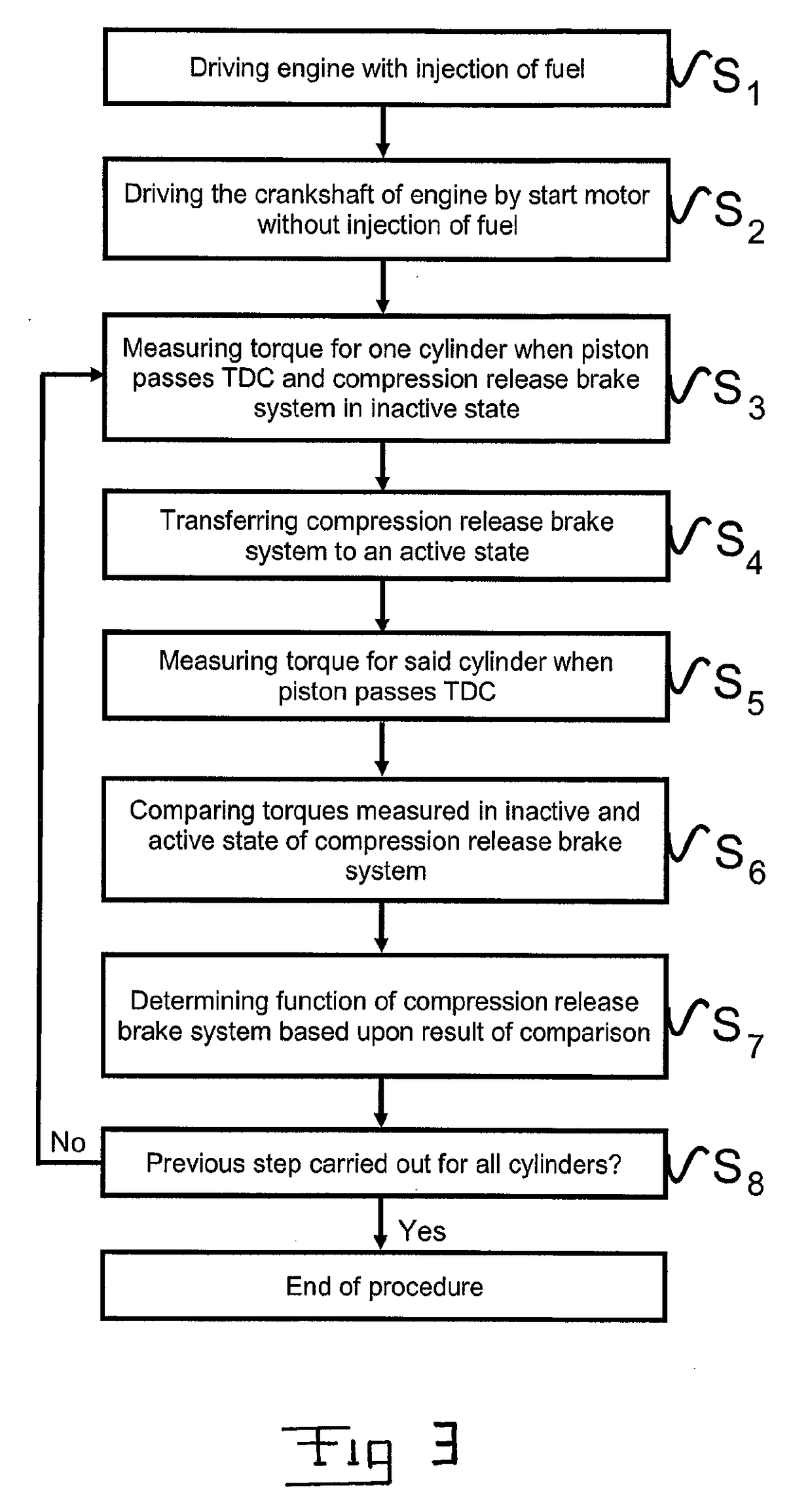
The patent describes a method for testing the function of a compression release brake system in an engine without using fuel. The method involves driving the crank shaft without injection of fuel and measuring the torque applied to maintain constant speed. The torque values are then compared between an active and an inactive state of the compression release brake system. This comparison can detect any malfunctions in the function of the compression release brake system for a particular cylinder. The method is simple, cost-effective, and can be carried out quickly.

Problems solved by technology

Such a compression ignited engine may offer poor possibilities to use engine braking when braking a motor vehicle.
However, the function of such a compression release brake system may of course for different reasons be degraded, which may for instance be due to a malfunction related to only one or a few of the cylinders of the engine, such as an incorrectly functioning valve rocker arm for the exhaust valve of such a cylinder which may depend upon an obstruction in an hydraulic line to a chamber to be filled with hydraulic fluid for triggering modified opening of the exhaust valve or a malfunction of an hydraulic valve controlling the supply of hydraulic fluid to a said chamber.
The driver of the vehicle may then bring the vehicle to a workshop and complain about the deteriorated braking effect of the compression release brake system.
However, the workshop will then not have any possibility to check the function of the compression release brake system, since it is only possible to activate this system when the engine is running and the system has the required hydraulic fluid pressure making it mostly impossible to point out for which of the cylinders the valve rocker arm associated with the exhaust valve does not function correctly when activating the compression release brake system.
This may then result in a replacement of said valve rocker arms for all the cylinders and a considerable unnecessary cost although perhaps only one valve rocker arm functions incorrectly when activating the compression release brake system.
However, the methods disclosed in these documents have the problem just mentioned with respect to pointing out for which of the cylinders the compression release brake system does not function would it be determined that the compression release brake system as a whole has a degraded function.

Method used


Image

  • Method for checking the function of a compression release brake system
  • Method for checking the function of a compression release brake system
  • Method for checking the function of a compression release brake system

Examples


Embodiment Construction

[0026]The invention is not restricted to a special type of motor vehicle, although the invention is particularly applicable to heavy wheeled motor vehicles, such as trucks or lorries and buses, and the invention will for that sake hereinafter primarily be discussed for that field of use for illuminating the invention but accordingly not in any way restrict it thereto.

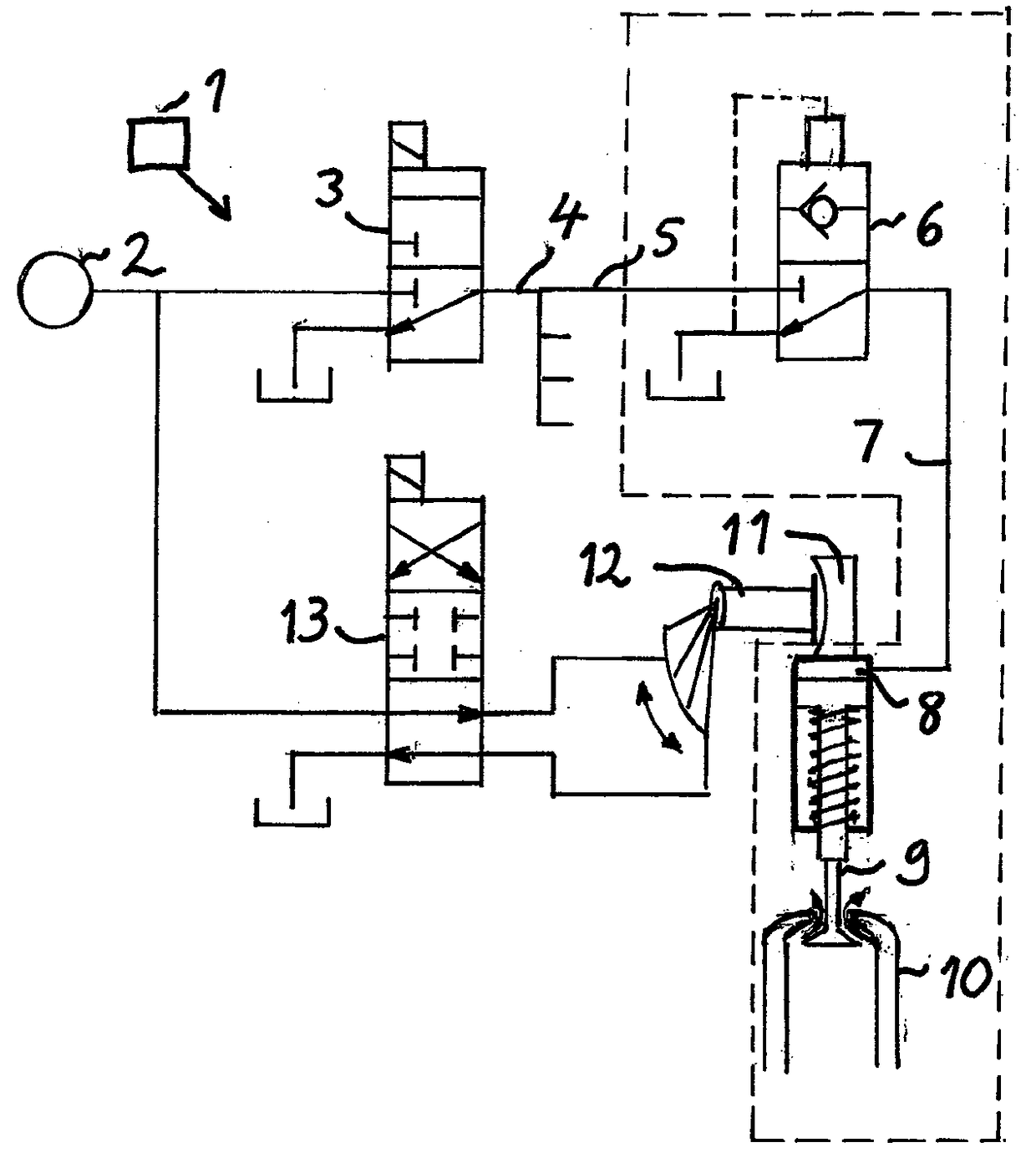
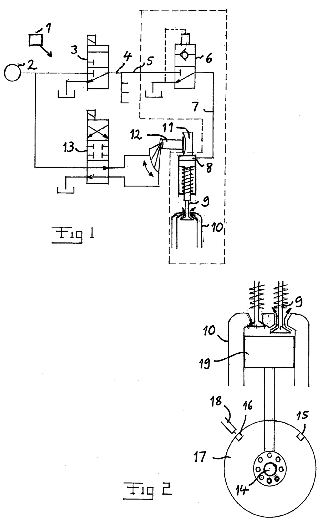
[0027]The general construction of a compression release brake system is schematically illustrated in FIG. 1. This system may be activated by an engine control unit 1 and is an hydraulic system with an hydraulic pump 2 supplying hydraulic fluid to a first solenoid valve 3 connecting to an hydraulic line 4 branched into as many lines as cylinders of the engine, and only one 5 of these lines and components associated therewith is shown in FIG. 1. This line 5 is connected to a control valve 6 connected through a line 7 to a chamber 8 in connection with a rocker arm valve 9 forming an exhaust valve of a cylinder 10 of said e...


PUM


Abstract

Function of a compression release brake system of a compression ignited engine with a plurality of cylinders in a motor vehicle is checked by driving a crank shaft of the engine to rotate at a constant speed without injection of fuel into the cylinders while for each cylinder, for the compression release brake system in an inactive state and then in an active state, measuring the torque to be applied for maintaining said speed in a position of said crank shaft where the torque would be influenced by the behavior of that cylinder by a correctly functioning action of said compression release brake system in an active state. The torque values obtained for each cylinder for the compression release brake system in inactive and active state are compared, and the function of the compression release brake system for each individual cylinder of the engine is determined based on the comparison.

Description

FIELD OF THE INVENTION[0001]The present invention relates to a method for checking the function of a compression release brake system of a compression ignited engine with a plurality of cylinders in a motor vehicle, said system comprising an arrangement configured, in an active state of said system, to influence opening of an exhaust valve of each said cylinder so as to obtain a braking action upon a crank shaft of the engine by influencing gas compression inside the cylinders.BACKGROUND[0002]The invention is not restricted to a special type of motor vehicle, although the invention is particularly applicable to heavy wheeled motor vehicles, such as trucks or lorries and buses, and the invention will for that sake hereinafter primarily be discussed for that field of use for illuminating the invention but accordingly not in any way restrict it thereto.[0003]The fuel used in such an engine may be of any conceivable type and diesel and ethanol may be mentioned as examples. Such a compre...

Claims


Application Information

Patent Timeline
IPC IPC(8): F02D13/04F02D41/22F01L13/06F02D41/30
CPCF02D13/04F02D41/3017F02D2200/1002F01L13/065F02D41/221F02N11/08F02D2250/24F01L1/18F01L1/3442F01L2800/11F01L2820/042
Inventor RONNQVIST, PATRIKMORNER, FREDRIK
Owner SCANIA CV AB
Learn More