Timing signal generation device, electronic device, and moving object

Inactive Publication Date: 2017-06-29
SEIKO EPSON CORP
View PDF3 Cites 8 Cited by
  • Summary
  • Abstract
  • Description
  • Claims
  • Application Information

AI Technical Summary

Benefits of technology

The technical effect of this patent is to create a device that generates timing signals with less frequency fluctuation and can quickly synchronize with a reference timing signal when started again. It can be used in electronic devices and moving objects.

Problems solved by technology

In the synchronization signal generation device disclosed in JP-A-2012-129879, in a case where a phase difference between the GPS reference pulse and the internal pulse is large, when the loop time of the synchronization unit is set to have a small value, a problem in that an output frequency largely fluctuates may occur.

Method used


Image

  • Timing signal generation device, electronic device, and moving object
  • Timing signal generation device, electronic device, and moving object
  • Timing signal generation device, electronic device, and moving object

Examples


first embodiment

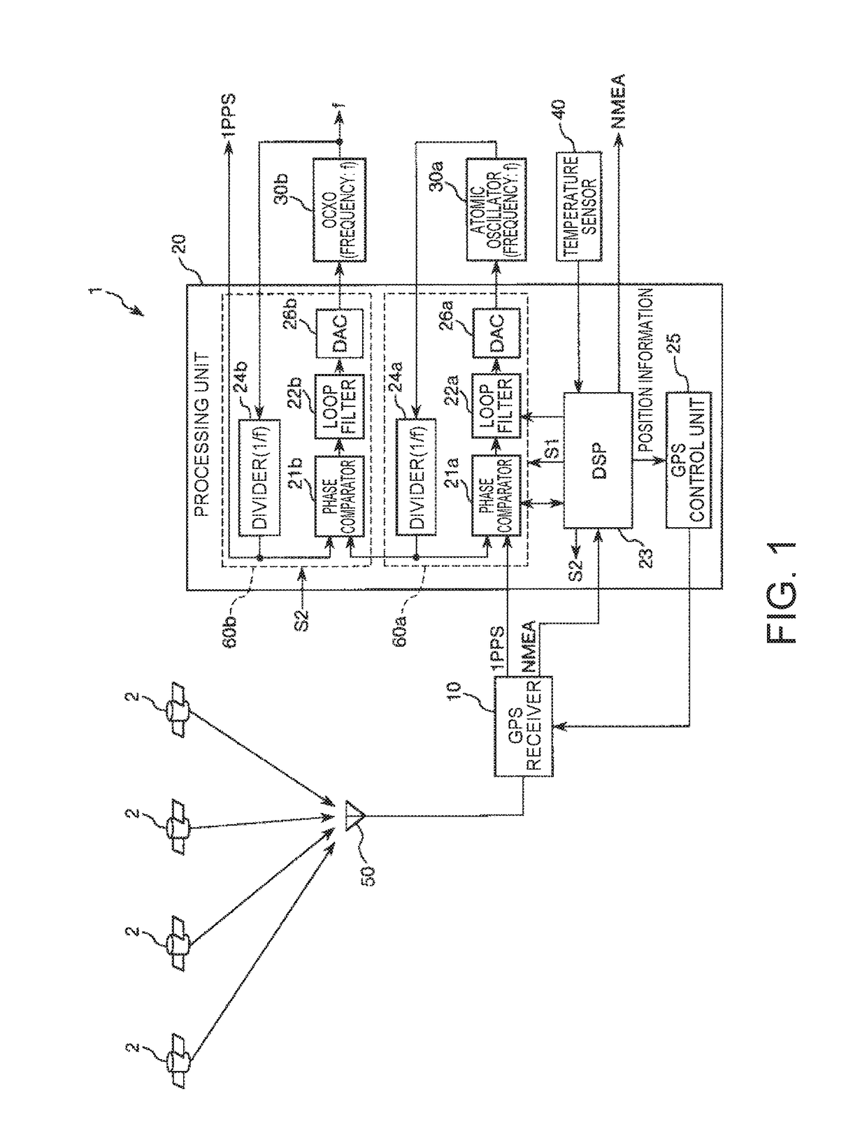
[0053]FIG. 1 is a schematic diagram illustrating a configuration of a timing signal generation device according to a first embodiment of the invention.

[0054]A timing signal generation device 1 illustrated in FIG. 1 includes a GPS receiver (reference-timing signal output unit) 10, a processing unit (CPU) 20, an atomic oscillator (first oscillator) 30a, an oven-controlled crystal oscillator (OXCO) (second oscillator) 30b, a temperature sensor 40, and a GPS antenna 50.

[0055]Some or all of the components of the timing signal generation device 1 may be physically separated or may be integrated. For example, each of the GPS receiver 10 and the processing unit (CPU) 20 maybe realized by using an individual IC. The GPS receiver 10 and the processing unit (CPU) 20 may be realized as a one-chip IC.

[0056]The timing signal generation device 1 receives a satellite signal transmitted from a GPS satellite (an example of a position information satellite) 2, and generates 1 PPS with high precision.

[...

second embodiment

[0145]FIG. 11 is a flowchart illustrating an operation of a first synchronization unit when synchronization is started, in a timing signal generation device according to a second embodiment of the invention.

[0146]This embodiment is similar to the above-described first embodiment except for different control of the second synchronization unit in GPS reset.

[0147]In the following descriptions, descriptions relating to the second embodiment will be made focused on different points from the above-described embodiment, and descriptions for similar items will be omitted. In FIG. 11, components similar to those in the above-described embodiment are denoted by the same reference signs.

[0148]In this embodiment, firstly, the processes of Steps S41 and S42 are performed similarly to the above-described first embodiment. Then, the time-constant adjustment unit 234 reduces the time constant of the loop filter 22a (Step S47).

[0149]Then, the determination unit 231 determines whether or not the phas...

third embodiment

[0152]FIG. 12 is a block diagram illustrating a control system of a first synchronization unit and a second synchronization unit in a timing signal generation device according to a third embodiment of the invention.

[0153]This embodiment is similar to the above-described first embodiment except that the time constant of the second loop filter can be adjusted.

[0154]In the following descriptions, descriptions relating to the third embodiment will be made focused on different points from the above-described embodiment, and descriptions for similar items will be omitted. In FIG. 12, components similar to those in the above-described embodiment are denoted by the same reference signs.

[0155]A DSP 23A according to this embodiment includes a determination unit 231A, a first count reset unit 232, a second count reset unit 233, a time-constant adjustment unit 234, and a time-constant adjustment unit (second time-constant adjustment unit) 235. The determination unit 231A performs determination ...


PUM


Abstract

A timing signal generation device includes a PLL circuit that synchronizes a first clock signal of an atomic oscillator with a reference timing signal of a GPS receiver, a PLL circuit that synchronizes a second clock signal of an oven-controlled crystal oscillator with the first clock signal, a first count reset unit that enables resetting of a count value of a divider in the PLL circuit when an operation of the PLL circuit is restarted, and a second count reset unit that enables resetting of a count value of a divider in the PLL circuit when the operation of the PLL circuit is restarted.

Description

CROSS REFERENCE[0001]This application claims the benefit of Japanese Application No. 2015-252783 filed on Dec. 25, 2015. The disclosure of the prior application is hereby incorporated by reference herein in its entirety.BACKGROUND[0002]1. Technical Field[0003]The present invention relates to a timing signal generation device, an electronic device, and a moving object.[0004]2. Related Art[0005]A timing signal generation device which performs synchronization with a precise timing signal included in a satellite signal and the like from, for example, a global positioning system (GPS) satellite, causes an oscillator such as a crystal oscillator or an atomic oscillator to oscillate, and thus generates a highly-precise timing signal has been known (for example, see JP-A-2012-129879).[0006]In such a timing signal generation device, when, for example, a situation in which reception of the satellite signal is not possible occurs, generally, synchronization processing of synchronizing a clock ...

Claims


Application Information

Patent Timeline
IPC IPC(8): H03L7/26G01S19/37H03L1/02
CPCH03L7/26H03L1/027G01S19/37H03B17/00H03L7/099H03L7/23
Inventor SHIMADA, HIROYUKI
Owner SEIKO EPSON CORP
Why Eureka
Try Eureka