
Circuit device, oscillator, electronic apparatus, and moving object

a technology of oscillator and circuit device, which is applied in the direction of oscillator generator, electrical apparatus, pulse automatic control, etc., can solve the problems of inability to achieve temperature compensation with high accuracy, small ambient temperature, and variable sensing temperature range, and achieve low temperature dependence of oscillation frequency and high stability of oscillation frequency

Active Publication Date: 2017-07-06
SEIKO EPSON CORP
View PDF3 Cites 14 Cited by
  • Summary
  • Abstract
  • Description
  • Claims
  • Application Information

AI Technical Summary

Benefits of technology

The invention provides a circuit device, oscillator, and electronic apparatus that can achieve a stable oscillation frequency with low temperature dependence. This means that the frequency of oscillation is less sensitive to changes in temperature.

Problems solved by technology

Therefore, although affected by the ambient temperature, if the temperature sensor incorporated in the circuit device is used alone, the variation range of the sensing temperature due to the variation in the ambient temperature becomes small, and the temperature compensation with high accuracy cannot be achieved.
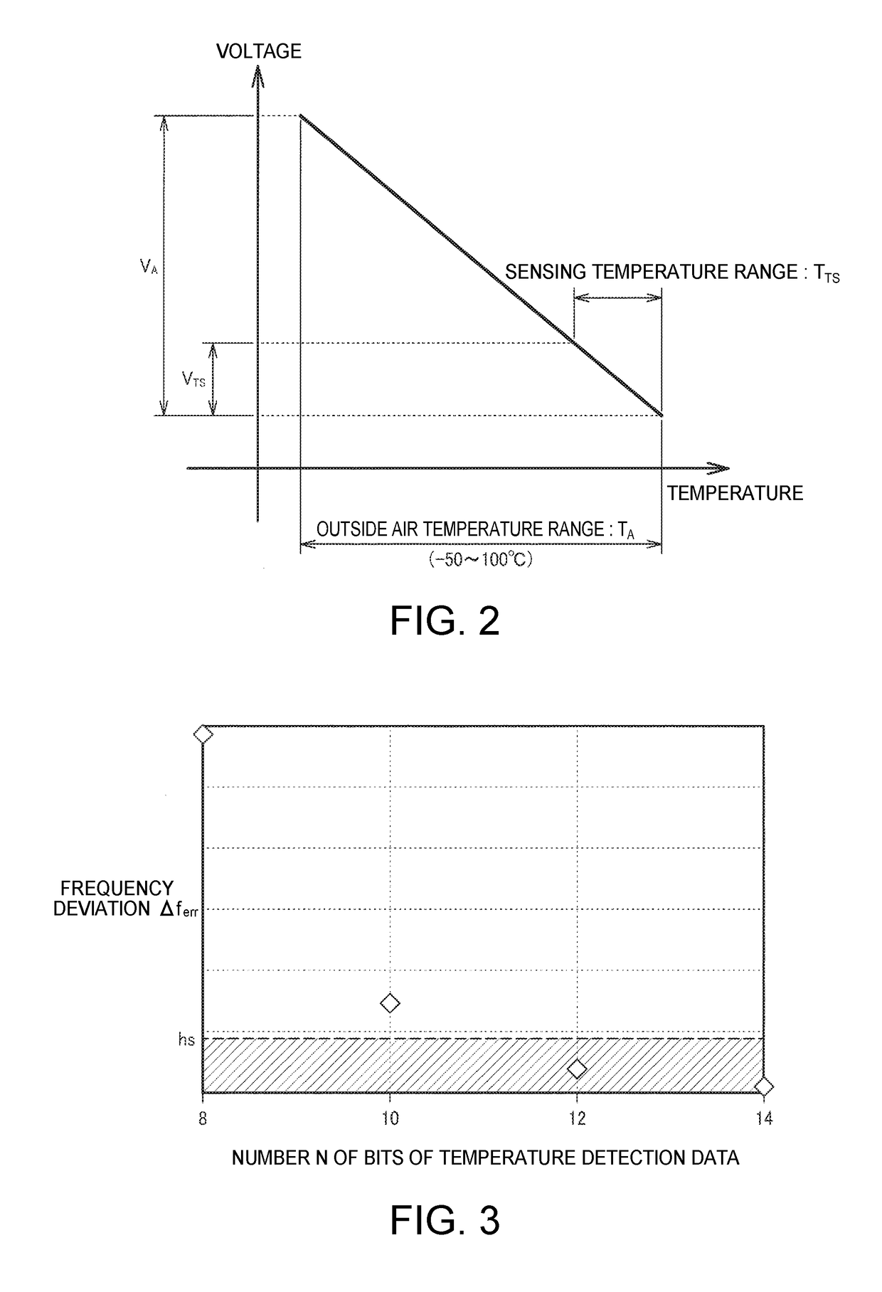
In this case, since the variation range of the sensing voltage becomes extremely small with respect to the input full scale of the A / D conversion circuit, the resolution of the A / D conversion circuit becomes low (the code variation range with respect to the variation range of the sensing voltage becomes small), and there is a possibility that the temperature compensation with high accuracy cannot be achieved.
Further, since there is provided the programmable gain amplifier, the noise in the temperature detection voltage is amplified by the gain thereof.
If the temperature compensation process is performed using the temperature detection voltage including the noise, it results that the noise is included in the frequency control data, and thus, the characteristic (e.g., the phase noise) of the oscillation signal is deteriorated.
However, since the temperature variation is small in the double oven, if the temperature sensor incorporated in the circuit device is used, the frequency correction error in the temperature compensation becomes larger.

Method used


Image

  • Circuit device, oscillator, electronic apparatus, and moving object
  • Circuit device, oscillator, electronic apparatus, and moving object
  • Circuit device, oscillator, electronic apparatus, and moving object

Examples


Embodiment Construction

[0052]Hereinafter, one or more embodiments of the invention will be described in detail. It should be noted that the one or more embodiments described hereinafter does not unreasonably limit the various embodiments of the invention as set forth in the appended claims, and all of the constituents described in the one or more embodiments are not necessarily essential as means of all of the embodiments for solving the problems.

1. Configuration

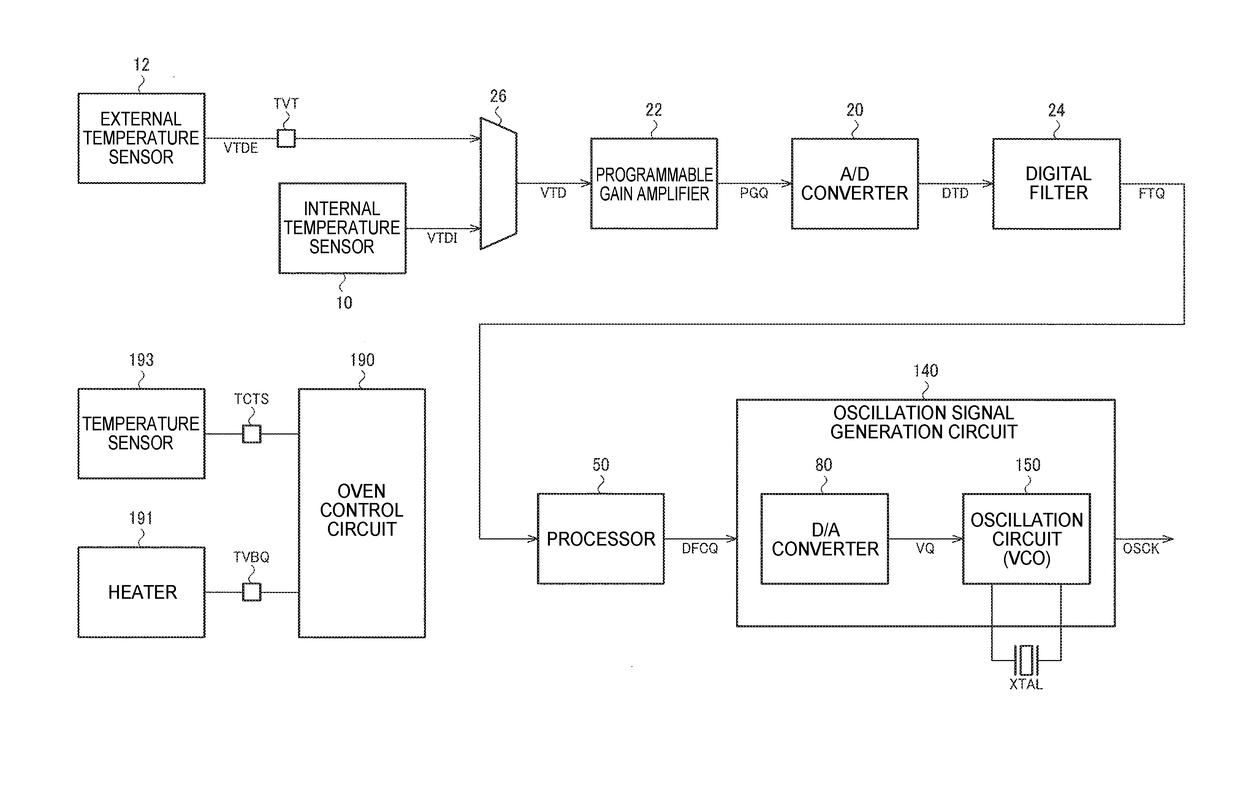
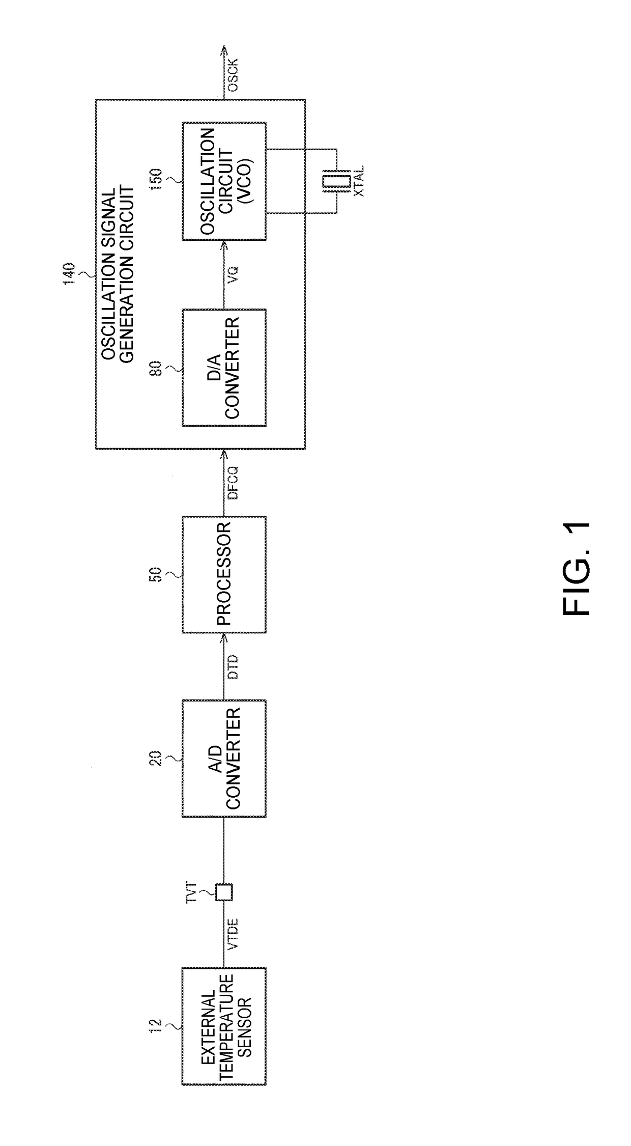
[0053]FIG. 1 shows a configuration example of a circuit device according to the present embodiment. The circuit device includes a temperature sensor input terminal TVT, an A / D converter 20 (an A / D conversion circuit), a processor 50 (a digital signal processor, a processing circuit), and an oscillation signal generation circuit 140.

[0054]An external temperature sensor 12 (a first temperature sensor) outputs a temperature-dependent voltage varying in accordance with the environmental temperature as a temperature detection voltage VTDE. The external...


PUM


Abstract

A circuit device includes a processor adapted to perform a signal processing of temperature compensation of an oscillation frequency based on temperature detection data from an external temperature sensor disposed outside the circuit device to output frequency control data, and an oscillation signal generation circuit adapted to generate an oscillation signal with the oscillation frequency corresponding to the frequency control data using the frequency control data and a resonator disposed in a thermostatic oven.

Description

CROSS-REFERENCE TO RELATED APPLICATIONS[0001]The present application claims priority to Japanese Patent Application JP 2016-001318, filed Jan. 6, 2016, the entire disclosure of which is hereby incorporated by reference herein.BACKGROUND[0002]1. Technical Field[0003]Various embodiments of the present invention relate to a circuit device, an oscillator, an electronic apparatus, a moving object, and so on.[0004]2. Related Art[0005]In the past, there has been known an oscillator such as an oven controlled crystal oscillator (OCXO), and a temperature compensated crystal oscillator (TCXO). For example, the OCXO is used as a reference signal source in a base station, a network router, a measurement device, or the like.[0006]As the related art of such an oscillator, there exists, for example, a technology disclosed in JP-A-2015-82815. In the related art, an aging correction of the oscillation frequency is performed in order to increase the accuracy of the oscillation frequency. Specifically...

Claims


Application Information

Patent Timeline
Patent Type & Authority Applications(United States)
IPC IPC(8): H03L1/02H03B5/32
CPCH03B5/32H03L1/02H03L1/022H03L1/04H03L1/023H03L1/028H03L7/093H03L7/099H03L7/0991H03L1/00
Inventor YONEZAWA, TAKEMI
Owner SEIKO EPSON CORP
Learn More