
Method and system of optical fibre with switching of modes and/or cores

a technology of optical fibre and core, applied in the field of optical telecommunications, can solve the problems of increasing sensitivity, and substantially limiting the range of these systems

Active Publication Date: 2017-07-06
INST MINES TELECOM
View PDF11 Cites 13 Cited by
  • Summary
  • Abstract
  • Description
  • Claims
  • Application Information

AI Technical Summary

Benefits of technology

The present invention relates to a system for optical transmission over multimode fiber using a spatio-temporal encoder and modulators. The system includes amplifiers and a mode scrambler to improve the transmission of laser beams through the fiber. The spatio-temporal encoder transforms each block of symbols into a code matrix related to time of use and propagation mode of the fiber. The modulators modulate the laser beams for transmission in the various modes of the fiber. The system can be used for optical transmission over multicore fiber with slices between the modes. The technical effects of the invention include improved transmission of laser beams through the fiber and reduced mode dispersion.

Problems solved by technology

Mode-dependent loss (MDL) Llp leads to increased sensitivity to noise sources, which may substantially limit the range of these systems.
Like the intermode coupling mentioned above, intercore coupling limits the range of these systems.
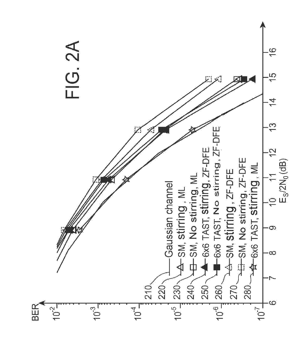
However, for one and the same signal-to-noise ratio, the bit error rate still remains higher than that which would be observed for an additive Gaussian channel.

Method used


Image

  • Method and system of optical fibre with switching of modes and/or cores
  • Method and system of optical fibre with switching of modes and/or cores
  • Method and system of optical fibre with switching of modes and/or cores

Examples


second embodiment

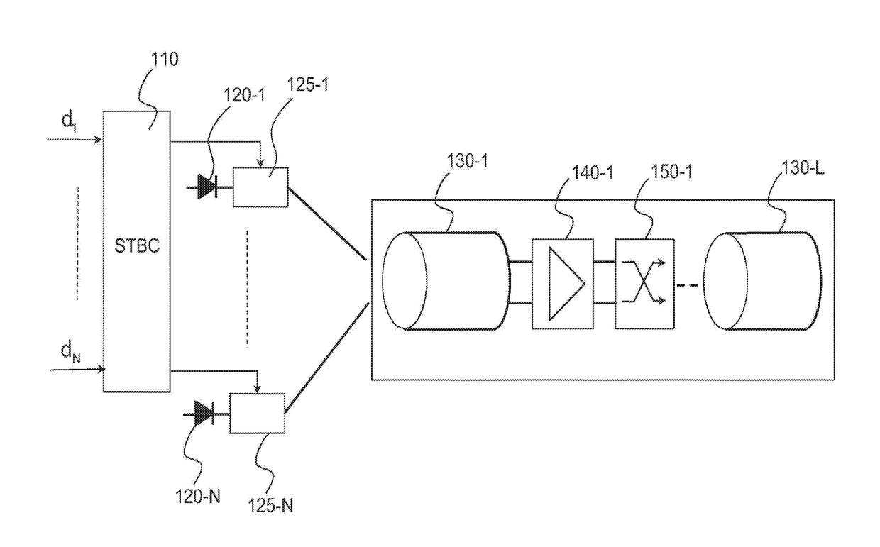
[0086]FIG. 4 schematically shows a system for transmission over optical fiber according to the invention.

first embodiment

[0087]In contrast to the first embodiment, the fiber used is, in this instance, of multicore type.

[0088]The optical transmission system comprises a spatio-temporal encoder 410, identical to the spatio-temporal encoder 110, N lasers 420n, n=1, . . . , N, of the same wavelength, or else alternatively a single laser whose beam is split into N separate beams. The beams are respectively modulated by the various outputs of the spatio-temporal encoder by means of the modulators 425n, n=1, . . . , N. The optical beams thus modulated are respectively injected into the various cores of the fiber. This injection may be achieved either by means of an optical device in free space or by means of a guided optics multiplexer.

[0089]The multicore fiber 430 comprises a plurality L of slices, 430l, l=1, . . . , L, an amplifier 440k being provided between each pair of consecutive slices 430l and 430l+1. Each amplifier 440l is associated with a core scrambler, 450l, located upstream or downstream of the ...


PUM


Abstract

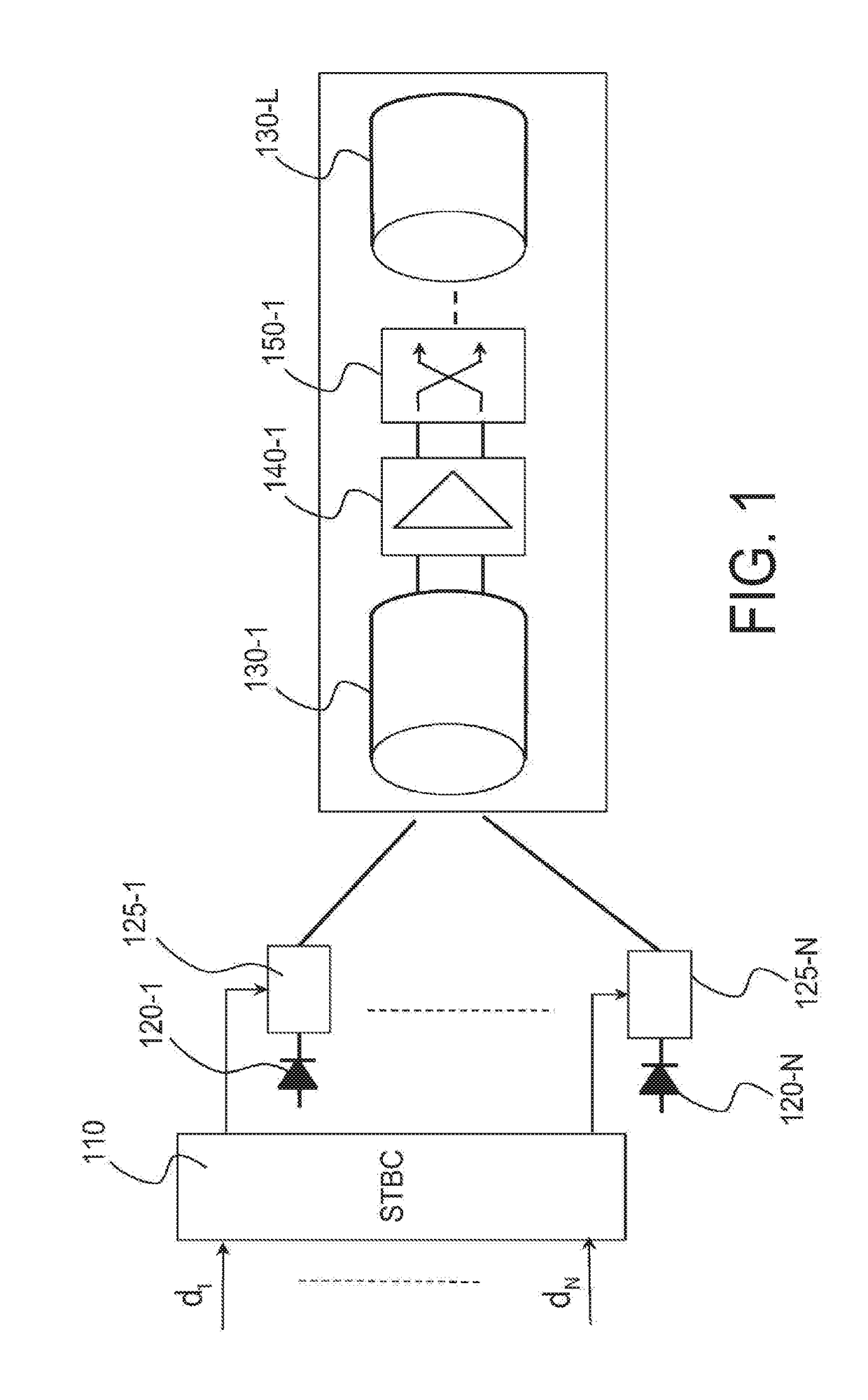
The invention relates to a system and a method for transmission over optical fiber (130) with mode or core scrambling. The system comprises a spatio-temporal encoder (110) and a plurality of modulators (1251, . . . , 125n) associated, respectively, with separate propagation modes or cores of said fiber, each modulator modulating a laser beam. Said fiber comprises a plurality of slices (1301, . . . , 130L), an amplifier (140l) being provided between any two consecutive slices of the optical fiber. A mode scrambler (150l) is associated with each amplifier in order to perform a permutation of said modes between at least two consecutive slices.

Description

TECHNICAL FIELD[0001]The present invention generally relates to the field of optical telecommunications and, more particularly, to those using optical fibers of multimode or multicore type.[0002]Prior Art[0003]Optical transmissions over long distance (several hundred to several thousand km) use single-mode optical fibers. These have the advantage of not exhibiting modal dispersion (apart from polarization mode dispersion) and of being able to handle high bitrates of many tens of Gbit / s per wavelength, even for a plurality of wavelengths.[0004]However, for transmissions over short distances, in particular for wideband local area networks (LANs), multimode or multicore fibers constitute a particularly advantageous alternative to single-mode fibers. It is possible to distinguish between two types of multimode fibers: plastic fibers (or POF) and silica fibers. The first are generally used along with simple energy detection at the end of the line, without multiplexing the data over the v...

Claims


Application Information

Patent Timeline
IPC IPC(8): H04B10/2581
CPCH04B10/2581H04J14/052H04B10/505H04B10/2507H04J14/04
Inventor AWWAD, ELIEREKAYA-BEN OTHMAN, GHAYAJAOUEN, YVES
Owner INST MINES TELECOM
Learn More