Wireless aviation headset

a wireless aviation and headset technology, applied in the field can solve the problems of limited reduced speech intelligibility, and restricted cord connections that restrict or limit user movement, so as to reduce noise, reduce speech intelligibility, and reduce the availability of wireless aviation headsets.

Inactive Publication Date: 2017-07-06
LIGHT SPEED AVIATION
View PDF14 Cites 3 Cited by
  • Summary
  • Abstract
  • Description
  • Claims
  • Application Information

AI Technical Summary

Benefits of technology

The patent text describes a system and method for wireless aviation communication between a user and an aircraft panel that reduces delay or latency in the process of hearing a sidetone. The system combines analog and digital wireless links to provide a high-quality audio signal while minimizing impact on speech intelligibility and user experience. The system also includes a mono signal for selected voice frequencies to improve speech intelligibility and maintain high-quality stereo sound for music playback. The battery status is indicated through LEDs and audible alerts, and the user is aware of a low battery condition, allowing them to optionally use a backup cord to connect the headset directly to the aircraft panel. Overall, the system provides an improved user experience and allows for safer and reliable communication between the user and the aircraft panel.

Problems solved by technology

Cord connections necessarily restrict or limit movement of the user relative to the aircraft panel.
Availability of wireless aviation headsets has been limited due to various design challenges.
One such challenge with wireless aviation communication systems is that pilots rely on hearing a sidetone (reproduction of their own voice) after the audio signal has been sent to the aircraft intercom and returned back from the intercom.
With traditional wireless technology solutions the delay (latency) of sending the signal to the intercom and receiving the signal back from the intercom results in an audible delay that reduces speech intelligibility.

Method used


Image

  • Wireless aviation headset
  • Wireless aviation headset
  • Wireless aviation headset

Examples


Embodiment Construction

[0016]As required, detailed embodiments are disclosed herein; however, it is to be understood that the disclosed embodiments are merely representative and the claimed subject matter may be embodied in various and alternative forms. The figures are not necessarily to scale; some features may be exaggerated or minimized to show details of particular components. Therefore, specific structural and functional details disclosed herein are not to be interpreted as limiting, but merely as a representative basis for teaching one skilled in the art to variously employ the claimed subject matter.

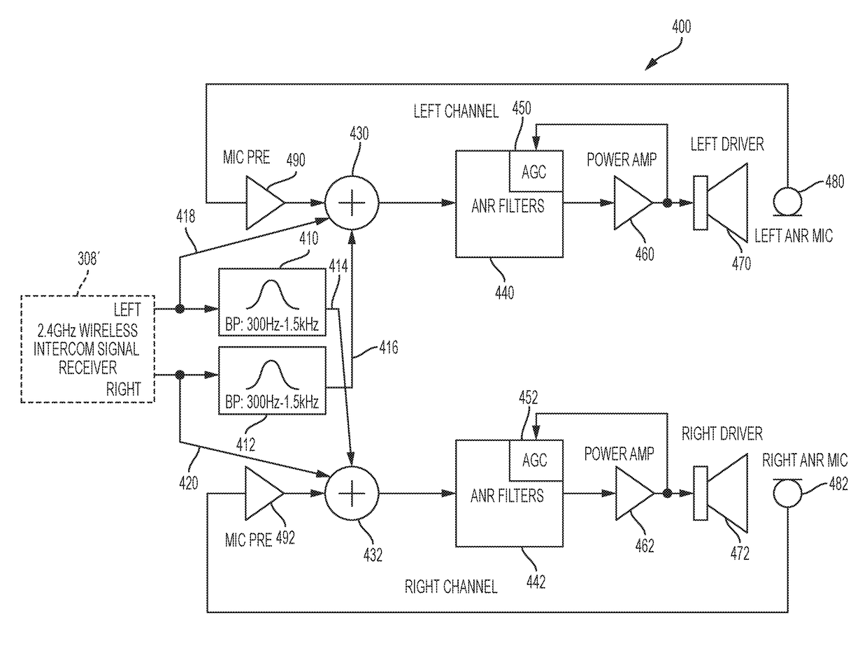
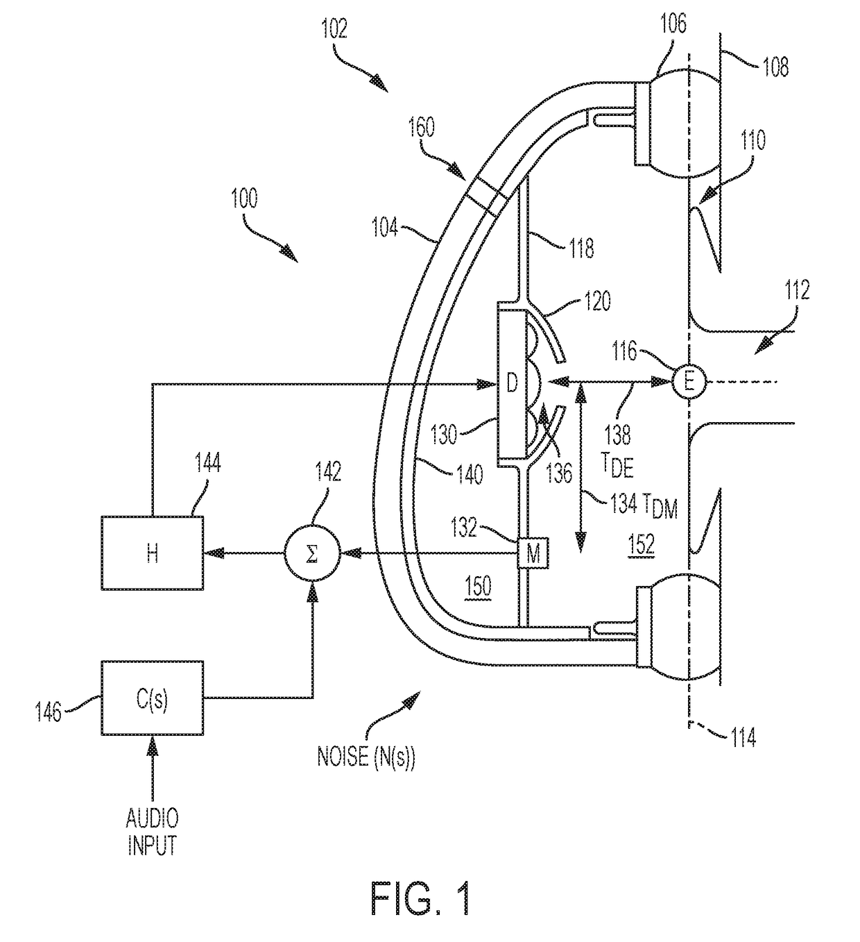
[0017]The representative embodiments used in the illustrations relate generally to wireless active noise reduction headphones or headsets that may be implemented by circumaural, supra-aural, or in-the-ear type devices. Similarly, representative embodiments include an audio microphone that may be positioned by an adjustable boom or may be attached or contained within another system component to capture ...


PUM


Abstract

An aircraft wireless communication system includes a headset having an active noise reduction (ANR) microphone, ANR circuitry coupled to the ANR microphone that generates a driver signal in response to the signal from the ANR microphone, a driver coupled to the ANR circuitry that receives the driver signal, a digital receiver coupled to the ANR circuitry, a voice microphone, and an analog transmitter coupled to the voice microphone. The system also includes an aircraft panel interface having an analog receiver that receives wireless signals from the analog transmitter and provides corresponding signals to a wired output configured to connect to an aircraft panel, and a digital transmitter connected to a wired input configured to connect to an aircraft panel and wirelessly transmit corresponding signals to the digital receiver. The system may include a left-to-right cross-feed circuit for selected frequencies to improve speech intelligibility.

Description

CROSS-REFERENCE TO RELATED APPLICATIONS[0001]This application claims the benefit of U.S. provisional application Ser. No. 62 / 253,129 filed Nov. 9, 2015, the disclosure of which is hereby incorporated in its entirety by reference herein.BACKGROUND AND SUMMARY[0002]Active noise reduction (ANR) or active noise cancellation (ANC) devices have been commercially available for many years. In general, these devices use electronics to generate a signal with the same amplitude but opposite phase of the noise. This is accomplished using a closed loop feedback and / or feedforward control system having a sensing microphone to detect the noise with the associated signal passed through electronics to drive a speaker that produces a pressure wave out of phase with the noise, resulting in a net reduction, attenuation, or cancellation of the noise perceived by a user.[0003]Many aviation headsets employ ANR technology to reduce noise associated with aircraft operation and to provide communication both ...

Claims


Application Information

Patent Timeline
IPC IPC(8): H04R5/033G06F3/16
CPCH04R5/033G06F3/162H04R2430/03H04R2201/107H04R2420/07H04R2460/01H04R1/1083
Inventor VAYNBERG, EDUARDELLIOT, JOHN C.
Owner LIGHT SPEED AVIATION
Why Eureka
Try Eureka