Vibration-proof structure of rotating body

Active Publication Date: 2017-07-13
DAISHOWA SEIKI CO LTD
View PDF7 Cites 7 Cited by
  • Summary
  • Abstract
  • Description
  • Claims
  • Application Information

AI Technical Summary

Benefits of technology

[0024]When vibration occurs in the rotating body such as a tool holder, the amount of displacement is larger at the center position in the longitudinal direction. With the above-described arrangement, three tubular members are provided as a set and the radial thickness of the tubular member disp

Problems solved by technology

Such device suffers a problem that when the blade portion on the leading end side comes into contact with a work, the tool holder is bent and deformed to cause vibration in the tool holder, thus leading to reduction i

Method used


Image

  • Vibration-proof structure of rotating body
  • Vibration-proof structure of rotating body
  • Vibration-proof structure of rotating body

Examples


first embodiment

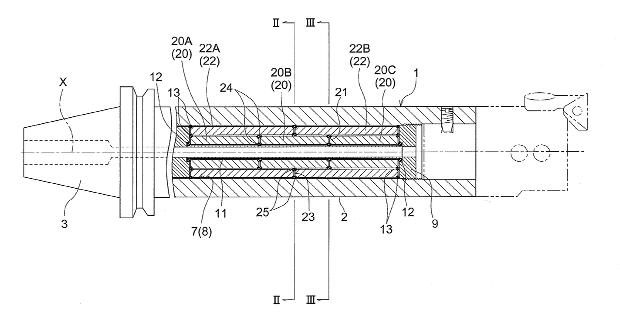
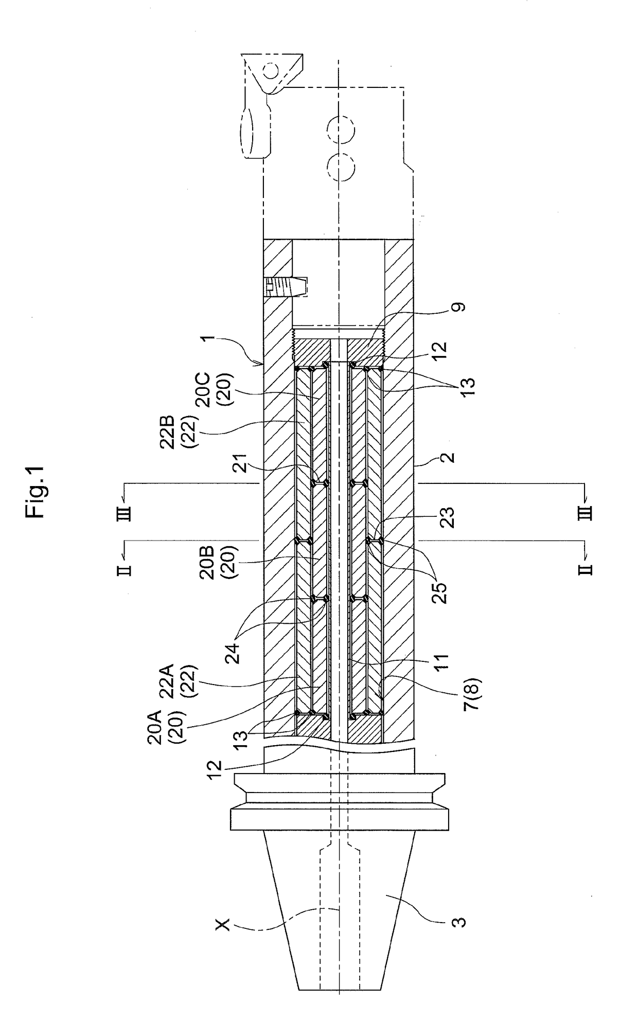
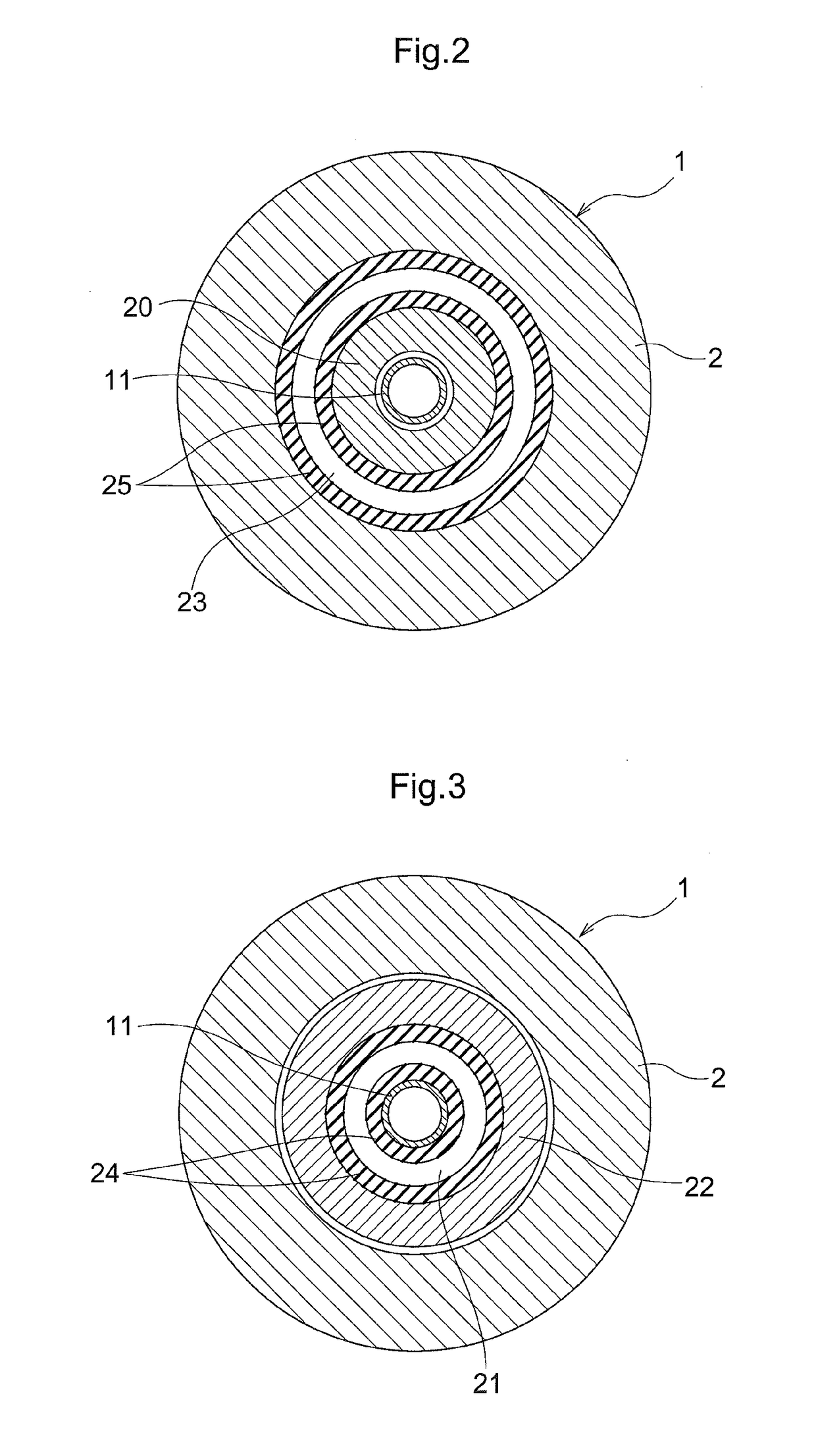
[0033]FIGS. 1 through 3 show a tool holder 1 (an example of “a rotating body”) having a vibration-proof structure according to the present invention.

[0034]This tool holder 1 is for a boring machining operation and includes a cylindrical elongate main body 2 to which a tool is attached, and a tapered shank portion 3 to be gripped to a spindle (not shown) of a machine tool.

[0035]The main body 2 includes therein a cylindrical hollow portion 7. This hollow portion 7 is formed by a shaft hole 8 which opens wide toward the leading end of the main body 2. In the shaft hole 8, a coolant pipe 11, shaft members 20 and tubular members 22 are disposed coaxially in the order from the center side of the hole.

[0036]On the outer circumference side of the coolant pipe 11, a plurality of cylindrical shaft members 20 are arranged along a longitudinal direction of a rotation axis X. FIG. 1 shows an example wherein three such shaft members 20 are disposed. On further outer side of the shaft members 20, ...

second embodiment

[0047]A second embodiment of the present invention is shown in FIG. 4. Here, a radial thickness of the tubular member 22 is set greater than a radial thickness of the shaft member 20. With this arrangement, the mass of the tubular member 22 is increased relative to the mass of the shaft member 20. Therefore, the inertial moment of the tubular member 22 is increased, so that the rotational state of the tubular member 22 is stabilized. As a result, the vibration absorbing function of the tool holder 1 is increased.

third embodiment

[0048]In this embodiment, as shown in FIG. 5, four shaft members 20 having an equal length a in the longitudinal direction are disposed and also on the outer side thereof, three tubular members 22 of an equal length are disposed. Here, the thickness of the tubular member 22B disposed centrally of the tubular members 22 is set greater than the thickness of the other tubular members 22A, 22C. As for the shaft members 20, the members 20A, 20D disposed at the extreme ends have a same thickness, whereas the center (intermediate) members 20B, 20C have a thickness which decreases at the center side in the longitudinal direction.

[0049]When vibration occurs in the tool holder 1, the amount of displacement will be larger at the longitudinal center position. Therefore, the vibration absorbing function is enhanced by the increase of the inertial moment of the tubular member 22B disposed in this region.


PUM


Abstract

Provided is a vibration-proof structure capable of more effectively reducing rotational vibration of a rotating body during a cutting operation. According to a configuration of the structure, inside a main body of the rotating body, there are provided a plurality of shaft members arranged along a longitudinal direction of a rotation axis of the rotating body and at least one layer of multiple tubular members fitted over the shaft members and arranged coaxially with the rotation axis along the longitudinal direction of this rotation axis; and a boundary position between the shaft members adjacent each other in the longitudinal direction and a boundary position between the tubular members adjacent each other in the longitudinal direction are set as different positions along the longitudinal direction.

Description

TECHNICAL FIELD[0001]The present invention relates to a vibration-proof structure of a rotating body which prevents vibration at the time of a rotary machining operation.BACKGROUND ART[0002]Conventionally, as a device for cutting a work formed of a metal or the like, there is known a device configured to hold an end portion side of a tool holder with a cutting blade portion fixed to its leading end and to rotate this tool holder. Such device suffers a problem that when the blade portion on the leading end side comes into contact with a work, the tool holder is bent and deformed to cause vibration in the tool holder, thus leading to reduction in machining precision. Such vibration differs in its mode, depending on the length or outer dimensions of the tool holder or property of material constituting the tool holder, etc.[0003]For this reason, e.g. Patent Document 1 shows a case in which for obtaining a large damping ratio for a wide range of vibration frequency, a boring bar for use ...

Claims


Application Information

Patent Timeline
IPC IPC(8): B23B29/02
CPCB23B2229/00B23B29/022B23B27/002B23B2250/16B23Q11/0032B24B41/007F16F15/08F16F15/1201B23B29/02B23C9/00F16F15/126B23B2250/04B23B2251/70B23C5/003B23D2277/10B23Q11/0039
Inventor NAKATANI, JOJIISHIDA, YASUYUKI
Owner DAISHOWA SEIKI CO LTD
Why Eureka
Try Eureka