Protection system for laser cutting machine

a protection system and laser cutting machine technology, applied in the direction of soldering apparatus, manufacturing tools, auxiliaries welding devices, etc., can solve the problems of laser cutting machine use imposing a number of hazards, affecting the safety of operators, so as to reduce the overall volume of the laser cutting machine and reasonable financial cost

Active Publication Date: 2017-07-13
MESTEK MACHINERY
View PDF0 Cites 18 Cited by
  • Summary
  • Abstract
  • Description
  • Claims
  • Application Information

AI Technical Summary

Benefits of technology

[0009]It is another object of the present invention to provide a protection system for a laser cutting machine that permits the operator of the laser cutting machine to directly load and unload the workpiece onto and off the table without having to wait for the pallet shuttle exit a typical protective enclosure apparatus.
[0010]It is another object of the present invention to provide a protection system for a laser cutting machine that allows the coil feeding of the workpiece directly onto the table at a reasonable financial cost.
[0011]It is another object of the present invention to provide a protection system of a laser cutting machine guard surround the laser torch head only and therefore reduce the overall volume of the laser cutting machine.

Problems solved by technology

Lasers enclosed in the laser cutting machines are capable of emitting high levels of energy and can therefore be dangerous to the eyes and skin of its operator.
The use of the laser cutting machine can also impose a number of hazards including toxic gases and fumes and inhalable particles.
Moreover, the possible random reflection of the laser light may burn the retina of an operator when the laser initially pierces the workpiece.
This not only results in a bulky machine, but also requires a pallet shuttle system to be installed onto the laser cutting machine for loading and unloading the workpiece into the chamber.
This solution drives up the financial cost as well as the operation time of the laser cutting machine.

Method used


Image

  • Protection system for laser cutting machine
  • Protection system for laser cutting machine
  • Protection system for laser cutting machine

Examples


Embodiment Construction

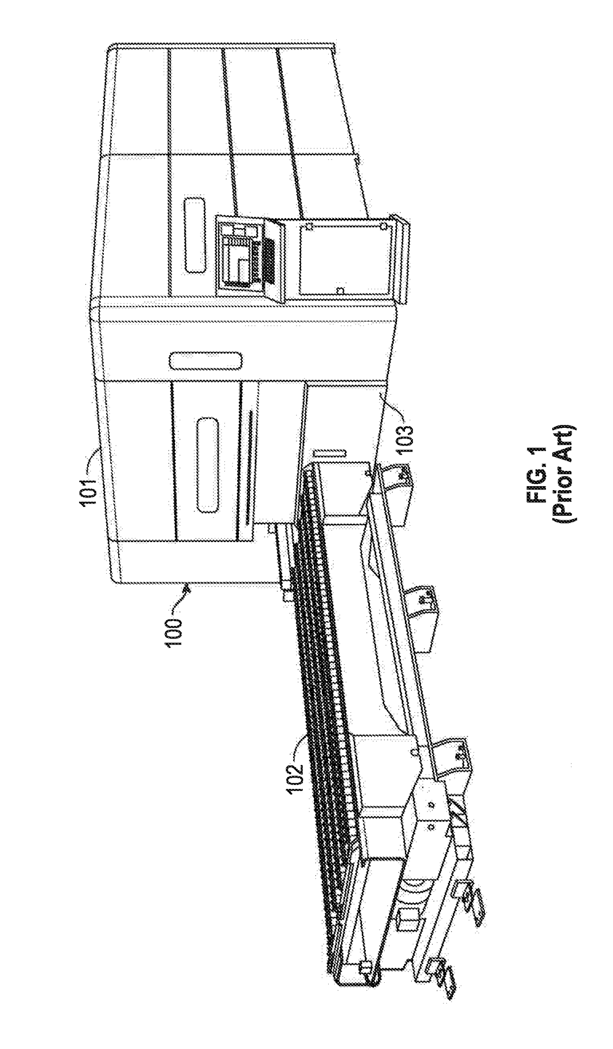
[0029]FIG. 1 illustrates an isomeric side view of a workpiece manipulation apparatus having a laser cutting machine, and its protective enclosure apparatus 100. A cutting laser (not shown) is positioned inside a protective enclosure apparatus 101. A pallet shuttle 102 locates in close association with the protective enclosure apparatus 101. A workpiece can be loaded and unloaded onto and off the pallet shuttle 102. The pallet shuttle 102 then carriers the loaded workpiece, enters into and exits the protective enclosure apparatus 101 through a protective enclosure apparatus enclosure door 103. In particular, to load and unload the workpiece to be processed by the laser cutting machine onto the pallet shuttle 102, the pallet shuttle 102 must exit the protective enclosure apparatus 101.

[0030]It will therefore be readily appreciated that known laser enclosures require enclosing the totality, or a great degree, of the workpiece manipulation apparatus itself, which is both expensive and c...


PUM

PropertyMeasurementUnit
distancesaaaaaaaaaa
semi-translucentaaaaaaaaaa
poweraaaaaaaaaa

Abstract

A laser cutting tool with protective enclosure assembly for manipulating a workpiece on a movable platen includes a frame, a top protection assembly, a middle protection shield, a bottom protection assembly and a laser torch head. The top protection assembly, middle protection assembly, and bottom protection assembly are removably mounted to the frame such that they form a cavity enclosing only substantially the laser torch head.

Description

CROSS-REFERENCE TO RELATED APPLICATIONS[0001]This application claims the benefit of U.S. Provisional Application Ser. No. 62 / 277,594, filed on Jan. 12, 2016, wherein is hereby incorporated by reference herein in its entirety.FIELD OF THE INVENTION[0002]The present invention relates generally to a protection system and more particularly, to a protection system for a laser cutting machine.BACKGROUND OF THE INVENTION[0003]Laser cutting is a technology that uses a laser to cut materials, and is typically used for industrial manufacturing applications. Laser cutting works by directing the output of a high-power laser most commonly through optics. A laser cutting machine features a cutting head generating a laser beam that moves in both of the horizontal dimensions over a workpiece loading onto a table. The focused laser beam is directed to the workpiece, part of which is then melted, burns, and vaporizes away. A cut edge with a high quality surface finish is therefore created.[0004]Laser...

Claims


Application Information

Patent Timeline
Patent Type & Authority Applications(United States)
IPC IPC(8): B23K26/70B23K26/38
CPCB23K26/38B23K26/706B23K37/006B23K26/0876B23K26/127B23K26/1462B23K37/0235F16P1/02F16P1/06B23K26/70
Inventor TIMMERMAN, BRYAN J.UMBERGER, CODY
Owner MESTEK MACHINERY
Why Eureka
Try Eureka