
Wireless rogowski coil system

a coil system and wireless technology, applied in the direction of current measurement only, measurement devices, instruments, etc., can solve the problems of inconvenient and difficult use of current measurement technique, inability to use clamp-on multimeters in confined spaces, and inability to meet the requirements of a single measurement, so as to reduce the potential adverse influence of parasitic factors and limit flexibility

Active Publication Date: 2017-07-13
JOHN FLUKE MFG CO INC
View PDF6 Cites 1 Cited by
  • Summary
  • Abstract
  • Description
  • Claims
  • Application Information

AI Technical Summary

Benefits of technology

The patent is for a wireless remote controlled Rogowski coil, a system that controls a sensor that measures the current in a conductor surrounded by a coil. This system includes an elongated Rogowski coil, an integrator circuit, an analog to digital converter, and a transceiver for wireless data transmission. The system can be controlled through a multimeter or other control apparatus that sends and receives control signals. The sensor unit has a memory and controller that can command the sensor to enter an idle mode and take readings of the current or periodically transmit readings. The technical effect is a more convenient and efficient way to measure current in a conductor.

Problems solved by technology

General purpose multimeters employing internal current shunts are generally limited to ten amperes maximum because of the capacity of the multimeter test leads and circuitry to carry the current.
In tight physical spaces such as an electrical cabinet, inserting the clamp-on multimeter and using this technique to make a current measurement is inconvenient and difficult.
Clamp-on multimeters are therefore difficult to use in confined spaces and require a large physical space in which to open the jaws of the current clamp.
Clamp-on multimeters also tend to be physically heavy because of the substantial amount of iron used on the magnetic core.
Furthermore, high levels of current may saturate the magnetic core.
The current measuring capacity of the clamp-on multimeter is accordingly limited to current levels that do not saturate the magnetic core.
However, the Rogowski coil is limited by the parasitic resistance, capacitance and inductance of the connecting cable.
The conductor may carry large voltage and currents that represent a danger to the technician because accidental contact with an exposed conductor could be harmful and possibly fatal.

Method used


Image

  • Wireless rogowski coil system
  • Wireless rogowski coil system
  • Wireless rogowski coil system

Examples


Embodiment Construction

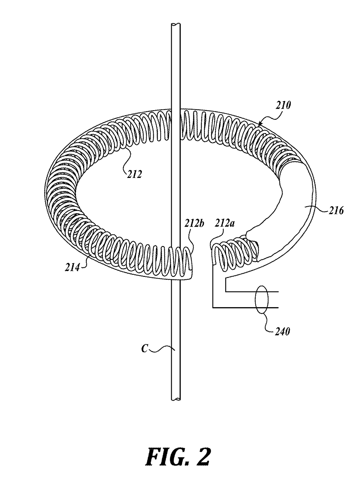
[0018]Specific details of embodiments according to the present disclosure are described below with reference to electrical circuits including a conductor. Other embodiments of the disclosure can have configurations, components, features or procedures different than those described in this section. A person of ordinary skill in the art, therefore, will accordingly understand that the disclosure may have other embodiments with additional elements, or the disclosure may have other embodiments without several of the elements shown and described below with reference to FIGS. 1-3.

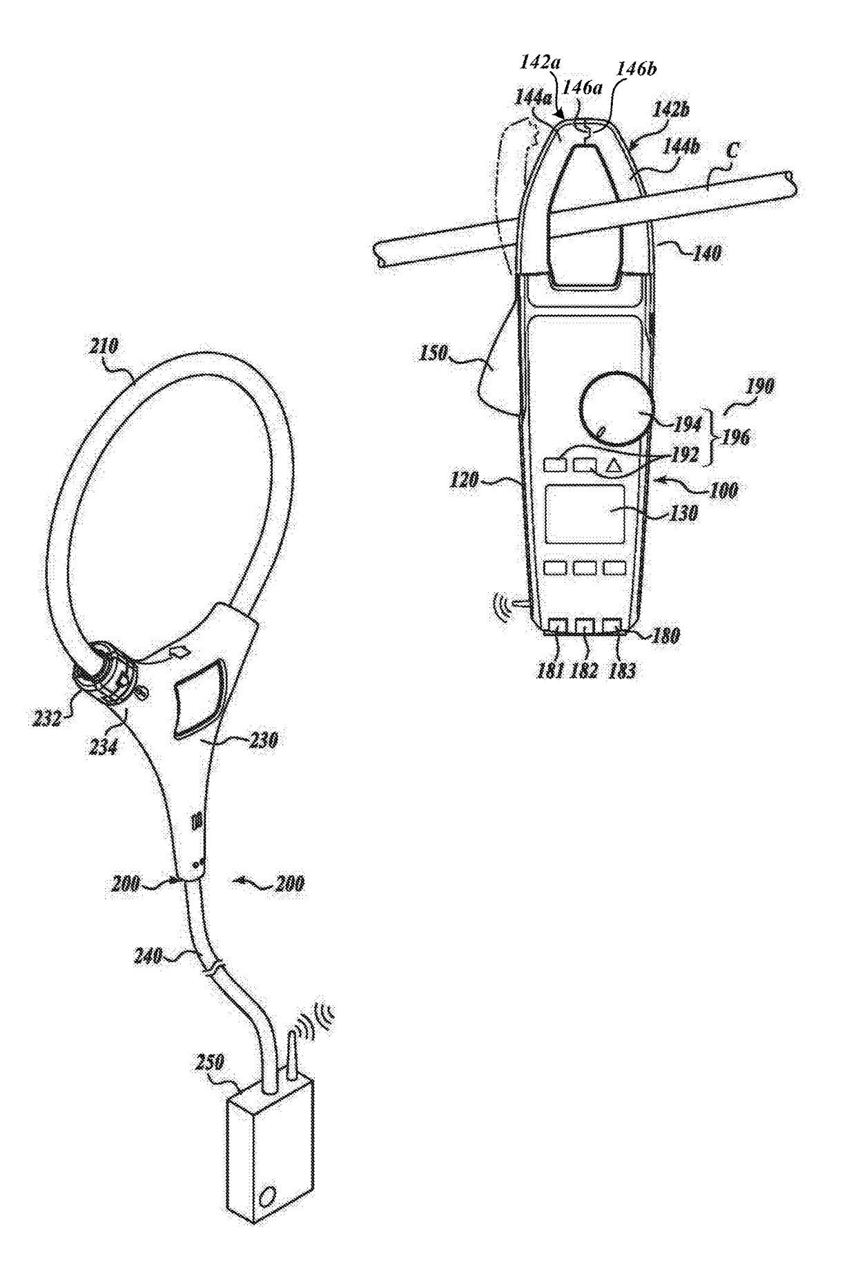
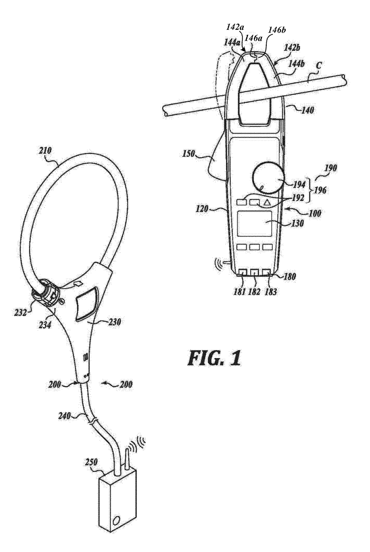
[0019]FIG. 1 is a schematic illustration of the multimeter 100 wirelessly coupled to the Rogowski coil sensor 200. The multimeter 100 includes a housing 120 having a slender shape whereby a user (not shown) is able to comfortably hold the housing 120.

[0020]A clamp 140 is provided on the housing 120. The clamp 140 includes a pair of clamp portions 142a and 142b having cores 144a and 144b, respectively. The clamp c...


PUM


Abstract

A Rogowski coil in a sensor unit has voltage induced by a conductor surrounded by the Rogowski coil. The voltage is integrated to represent current which is converted to digital data representing current in the conductor and sent wirelessly to a multimeter. The sensor unit may receive control signals from the multimeter and a remote control apparatus. A plurality of sensor units may be networked and controlled by the remote control apparatus.

Description

BACKGROUND[0001]Technical Field[0002]Systems and methods for measuring current in a conductor.[0003]Description of the Related Art[0004]Multimeters, also called digital multimeters or “DMMs,” are adapted for measuring a number of parameters generally needed for service, troubleshooting, and maintenance applications. Such parameters typically include a.c. (alternating current) voltage and current, d.c. (direct current) voltage and current, and resistance or continuity. Other parameters, such as frequency, capacitance, and temperature, may also be measured to meet the requirements of the particular application. In order to measure current with a general purpose multimeter, an internal current shunt having a known resistance must be inserted in the current path, requiring a break in the current-carrying conductor. The voltage drop across the current shunt is then measured to determine the current flow.[0005]General purpose multimeters employing internal current shunts are generally lim...

Claims


Application Information

Patent Timeline
Patent Type & Authority Applications(United States)
IPC IPC(8): G01R15/18G01R19/00G01R15/12
CPCG01R15/181G01R19/0092G01R15/125G01R15/12G01R31/3025
Inventor BANNISTER, MATTHEW CARL-ROBERTEPPERSON, DAVID LAWRENCEHUBER, CLARK N.
Owner JOHN FLUKE MFG CO INC
Learn More