Spray-formed high-speed steel

Active Publication Date: 2017-07-20
HEYE SPECIAL STEEL +1
View PDF1 Cites 1 Cited by
  • Summary
  • Abstract
  • Description
  • Claims
  • Application Information

AI Technical Summary

Benefits of technology

The present invention provides a spray-formed high-speed steel with uniform microstructure, fine carbides, and excellent comprehensive mechanical performances such as hardness, impact toughness, and bending strength. It is easy to process with machining and grinding. The spray-formed high-speed steel has a segregation of alloying elements restrained in a small range, a short preparation process flow, and a relatively low cost. It can be used to manufacture various cutters, such as turning tools, hobs, broaches, and drills, replacing high-speed steel prepared through a powder metallurgy process.

Problems solved by technology

Because of the slow cooling velocity during the casting process, the high-speed steel prepared through the conventional method has a serious segregation of the alloying elements, forming coarse crystalline grains and carbides.
Even after the subsequent thermal deformation process, the nonuniformity of the structure is difficult to be completely eliminated, thereby causing the performance of the high-speed steel at a relatively low level.
Although the powder metallurgy process has a relatively mature development, by which the high-quality high-speed steel is manufactured, the powder metallurgy process has the long process flow and the high manufacture cost and energy consumption, causing a high price of the product.
How to improve the product quality with the relatively low process cost is a technical problem required to be solved in the conventional high-speed steel preparation.
With spray forming, the size of the cross section of the ingot increases; during spray deposition, the solidification velocity of the liquid steel at the end of the ingot relatively decreases; and, for the high-speed steel having the characteristics of high melting temperature, wide solidification temperature range, and multiple phase compositions, the segregation of the alloying elements easily occurs at the local ingot, forming the coarse structure, which further affects the product quality.

Method used


Image

  • Spray-formed high-speed steel

Examples


first preferred embodiment

[0043]The first preferred embodiment relates to a group of spray-formed high-speed steel, and chemical components thereof are listed in Table 1.1.

TABLE 1.1chemical components of spray-formed high-speed steels in firstpreferred embodimentCSiCrWMoVNbCoMnSPEmbod-1.230.54.55.25.51.751.05.00.30.0030.02iment1.1Embod1.551.07.46.06.83.53.027.00.70.0040.02iment1.2Embod-0.900.23.54.24.61.320.552.50.20.0030.015iment1.3Embod-1.120.85.94.85.22.62.214.00.50.0050.02iment1.4

[0044]The embodiments 1.1-1.4 are prepared through the spray forming process. After finishing spray deposition, an ingot of about Φ500 mm is obtained. Through directly transferring the spray-deposited ingot for thermal deformation processing, a bar of Φ100 mm is obtained

second preferred embodiment

[0045]A structure, a hardness, and an impact toughness of a spray-formed high-speed steel in the first preferred embodiment are analyzed.

[0046]The hardness is contrastively analyzed through Rockwell hardness. The impact toughness is measured through a Charpy non-notch specimen method, and a size of an impact toughness test specimen is 10 mm×10 mm×55 mm.

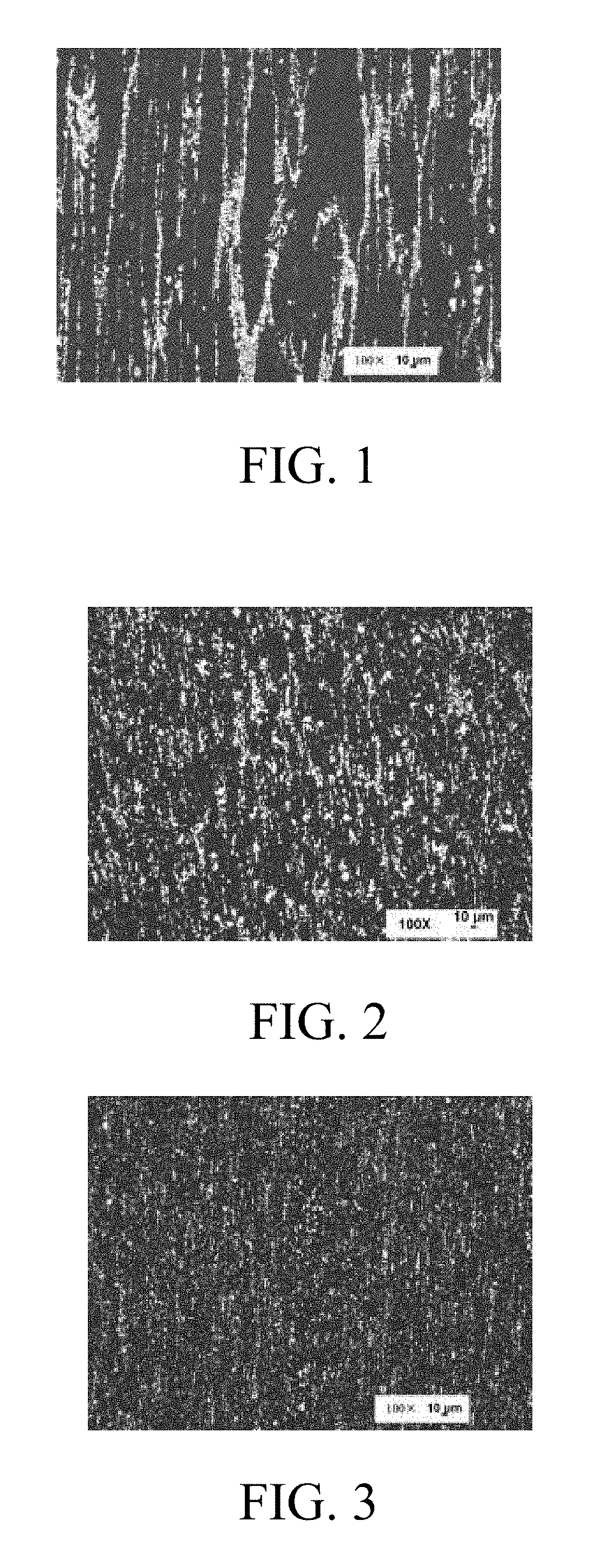
[0047]A spray-formed high-speed steel of embodiment 1.1, a high-speed steel bar (alloy A) of Φ100 mm which is bought commercially and prepared though an electroslag remelting and forging process, and a spray-formed bar (alloy B) of Φ100 mm which has different chemical compositions are contrastively analyzed, and results thereof are showed in Table 2.1.

TABLE 2.1component comparison of embodiment 1.1, alloy A and alloy BSteeltypeCSiCrWMoVNbCoMnSPAlloy A0.920.54.06.14.851.8—5.00.40.0020.02Alloy B1.10.53.81.49.31.1—8.00.40.0030.02Embod-1.230.54.55.25.51.751.05.00.30.0030.02iment1.1

[0048]Structures of the embodiment 1.1, the alloy A, and t...


PUM

PropertyMeasurementUnit
Fractionaaaaaaaaaa
Fractionaaaaaaaaaa
Fractionaaaaaaaaaa

Abstract

A spray-formed high-speed steel includes chemical components by mass percent of: C: 0.85-1.65%, Si: 0.1-1.2%, Cr: 3.5-8.0%, W: 4.0-6.5%, Mo: 4.5-7.0%, V: 1.0-4.0%, Co: 1.0-8.0%, Mn: 0.2-0.8%, and Nb: 0.2-3.5%, with balance of iron and impurities.

Description

CROSS REFERENCE OF RELATED APPLICATION[0001]This is a U.S. National Stage under 35 U.S.C 371 of the International Application PCT / CN2015 / 091273, filed on Sep. 30, 2015, which claims priority under 35 U.S.C. 119(a-d) to CN 201510249129.0, filed on May 15, 2015.BACKGROUND OF THE PRESENT INVENTION[0002]Field of Invention[0003]The present invention relates to a high-speed steel, and more particularly to a spray-formed high-speed steel.[0004]Description of Related Arts[0005]Because of the slow cooling velocity during the casting process, the high-speed steel prepared through the conventional method has a serious segregation of the alloying elements, forming coarse crystalline grains and carbides. Even after the subsequent thermal deformation process, the nonuniformity of the structure is difficult to be completely eliminated, thereby causing the performance of the high-speed steel at a relatively low level.[0006]In order to restrain the segregation of the alloying elements during process...

Claims


Application Information

Patent Timeline
IPC IPC(8): C22C38/30C22C38/24C22C38/02C22C38/04C22C38/00C22C38/26C22C38/22
CPCC22C38/30C22C38/26C22C38/24C22C38/02C22C38/04C22C38/002C22C38/22
Inventor WU, LIZHILI, XIAOMINGYANG, YUNFENGKUANG, CHUNJIANGXIN, DONGMEISHAO, LIQINGFANG, YUCHENG
Owner HEYE SPECIAL STEEL
Why Eureka
Try Eureka