
Vehicle Charging Station Comprising A Supply-Contact Device Mounted On An Arm

a technology of supply contact and charging station, which is applied in the field of electric vehicles, can solve the problems of reducing the payload of the vehicle, increasing the drive power, and lowering the devi

Inactive Publication Date: 2017-07-27
SIEMENS AG
View PDF0 Cites 7 Cited by
  • Summary
  • Abstract
  • Description
  • Claims
  • Application Information

AI Technical Summary

Benefits of technology

The present invention aims to solve problems associated with battery-based vehicles by providing a way to charge them without using a pantograph and by eliminating moving parts on the vehicle. This reduces weight and cleaning requirements, and also avoids failures caused by wear and tear. The invention also takes into account the positioning accuracy of the contact strips and compensates for asymmetrical loading conditions of the vehicle. Additionally, the invention enables better compensation for parking vehicle positioning by moving the individual members of the arm in a working or swivel plane.

Problems solved by technology

A disadvantage here is that the pantograph, together with the lifting and lowering device, has to be carried on the vehicle roof.
This calls for additional drive power and reduces the payload of the vehicle.
In addition, the lifting and lowering device comprises a plurality of moving parts and, on the roof, the device, together with the drive technology, is exposed to the weather and is susceptible to faults.
The design of the extendable pantograph on the vehicle roof also reduces the clearance height of the electric bus.
Manual switching operations are required for the charging process, which is undesirable.

Method used


Image

  • Vehicle Charging Station Comprising A Supply-Contact Device Mounted On An Arm
  • Vehicle Charging Station Comprising A Supply-Contact Device Mounted On An Arm
  • Vehicle Charging Station Comprising A Supply-Contact Device Mounted On An Arm

Examples


Embodiment Construction

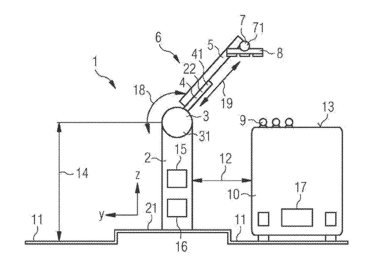
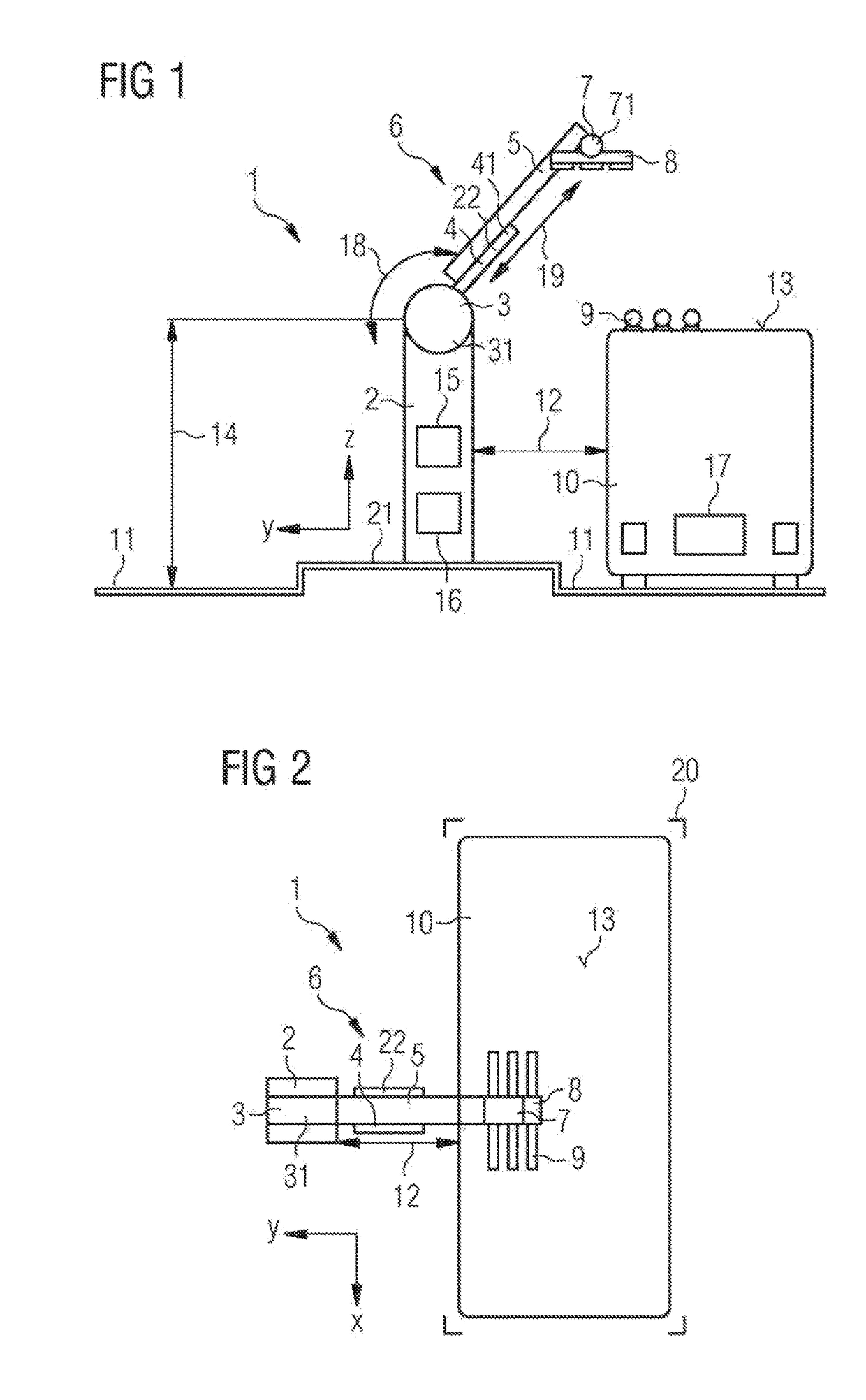
[0004]An object of the present invention is to avoid the aforementioned disadvantages and to establish an approach such that charging of the energy accumulator of a battery-driven vehicle is possible without a pantograph, together with the lifting and lowering device, having to be carried by the vehicle, and wherein the charging process is to a large extent automatable.

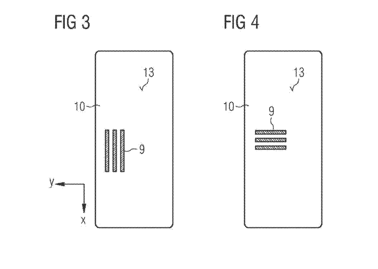
[0005]The object is achieved in a vehicle charging station for charging an energy accumulator of a battery-driven vehicle, in particular an electric bus or a hybrid vehicle, the vehicle parking in a pre-defined parking position during the charging process and having the following:[0006]a) a base which is arranged in the vicinity of the pre-defined parking position;[0007]b) an arm[0008]i. having a first member which extends longitudinally and one end of which is rotatably mounted in a revolute joint situated on the base and is rotary driven by means of a rotary drive,[0009]ii. having a second member which is mounted in...


PUM


Abstract

A vehicle charging station charges an energy accumulator of a battery-driven vehicle. The charging station has a base which is arranged in the vicinity of a pre-defined parking position of the vehicle and an arm. The arm has a first member which extends longitudinally and one end is rotatably mounted in a revolute joint situated on the base and is rotary driven by a rotary drive and a second member mounted in a linear guide on the first member and moves in the direction of the longitudinal extension by a linear drive. The end of the second member facing away from the linear guide is connected to a supply-contact. A control unit controls the rotary drive and the linear drive, such that the supply-contact moves back and forth from an idle position into a working position, in which electrical contact is made between the supply-contact and a receiving-contact device.

Description

TECHNICAL FIELD[0001]The invention relates in general to the technical field of electric vehicles, in particular to a vehicle charging station and to a method for charging an energy accumulator in an electric vehicle.PRIOR ART[0002]In local public transportation, battery-driven transport systems have long been known, for example from DE 24 05 198. Fully electric buses, the entire energy requirements of which are covered by the battery system carried on the vehicle, have recently been put into service. In the metropolitan area of Vienna, fully electric buses of this type are currently in service which obtain their drive power completely from a plurality of lithium ferrite batteries carried on the vehicle, said batteries having a total capacity of approximately 100 kWh and being accommodated on the roof and / or at the rear of the vehicle. These batteries are recharged within approximately 15 minutes during service hours, in each case at a terminal station on the bus line, and overnight...

Claims


Application Information

Patent Timeline
Patent Type & Authority Applications(United States)
IPC IPC(8): B60L11/18H02J7/00
CPCB60L11/1827B60L11/1818B60L2200/18H02J7/0045H02J7/0027B60L9/00B60L53/16B60L53/31B60L53/30Y02T90/14H02J7/0042B60L53/35Y02T10/70Y02T10/7072Y02T90/12H02J2310/48
Inventor BUEHS, FLORIANROMPE, ANDRE
Owner SIEMENS AG
Learn More