
Method for using aircraft wheel tyre pressure to improve aircraft energy efficiency and drive system performance

a technology of aircraft tyre pressure and drive system performance, which is applied in the direction of process and machine control, instruments, navigation instruments, etc., can solve the problems of significant hazard risk for an operating vehicle, tyre useful life, and no suggestion of a relationship between efficient autonomous aircraft taxi and aircraft tyre pressure, so as to improve both drive system performance and aircraft energy efficiency

Active Publication Date: 2017-08-03
BOREALIS TECH LTD
View PDF25 Cites 8 Cited by
  • Summary
  • Abstract
  • Description
  • Claims
  • Application Information

AI Technical Summary

Benefits of technology

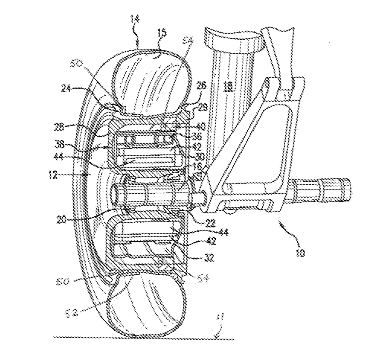
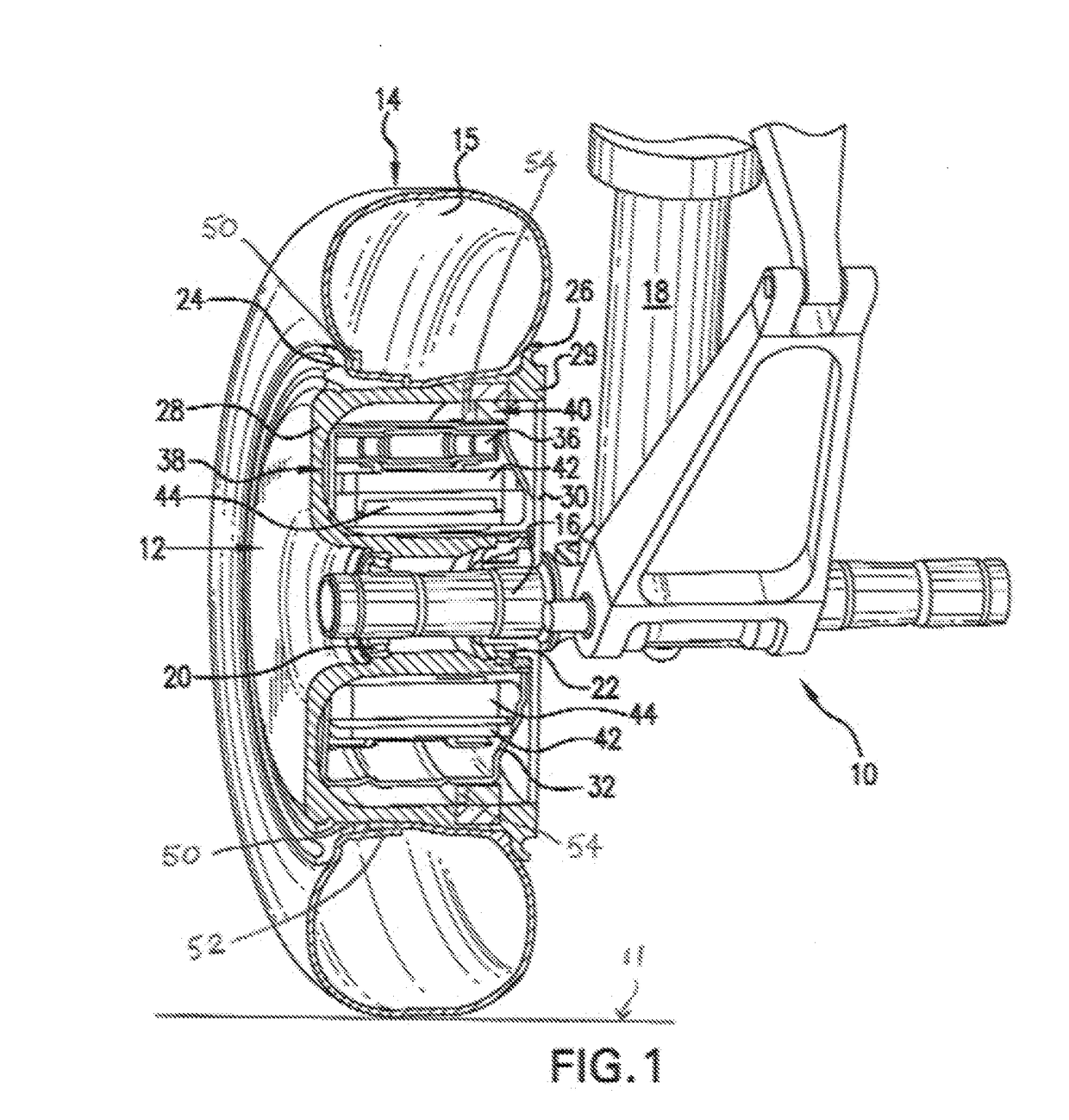
The present invention aims to improve the performance and energy efficiency of aircraft equipped with landing gear wheel drive assemblies during ground operations. It does this by maintaining the pressure of the aircraft's wheels' tires at an optimal level that enhances both the performance of the drive system and the aircraft's energy efficiency. This method can lead to significant fuel savings and can also involve adjusting the pressure of the tires to simulate a weight change or reducing engine energy consumption. Overall, the invention provides a way to improve performance and efficiency in aircraft equipped with landing gear wheel drive assemblies.

Problems solved by technology

Under- and over-inflated tyres are likely to fail as a result of stresses on tyre components, blowouts, or other causes and, consequently, can present a significant hazard risk for an operating vehicle.
Aircraft tyres have long been required to be filled with nitrogen gas, which both reduces fire risks and extends tyre useful life.
While the drive motors described in these patents can effectively move an aircraft autonomously without aircraft engines during ground operations, there is no suggestion of a relationship between efficient autonomous aircraft taxi and aircraft tyre pressure.

Method used


Image

  • Method for using aircraft wheel tyre pressure to improve aircraft energy efficiency and drive system performance
  • Method for using aircraft wheel tyre pressure to improve aircraft energy efficiency and drive system performance

Examples


Embodiment Construction

[0014]It is acknowledged in the airline industry that improperly inflated aircraft tyres can significantly compromise the safety of aircraft operations. As a result, the United States Federal Aviation Administration (FAA) and corresponding international aviation authorities continuously emphasize the importance of maintaining properly inflated aircraft tyres to prevent the occurrence of potentially catastrophic events. These authorities suggest that frequent tyre checks be conducted to ensure aircraft tyres remain inflated to within an inflation range, typically that specified in a maintenance manual for the aircraft. Since an aircraft tyre may lose up to five percent (5%) of tyre pressure a day under typical operations, frequent pressure checks are recommended to maintain correct tyre pressure and avoid premature tyre replacement. Ideally, tyre pressure should be checked at a time that enables maintenance of the recommended tyre pressure for each flight cycle.

[0015]Aircraft tyre ma...


PUM


Abstract

A method is provided for improving both landing gear wheel drive assembly performance and energy efficiency performance in an aircraft equipped with one or more landing gear wheel drive assemblies to move the aircraft autonomously on the ground without reliance on the aircraft's engines. Aircraft moved on the ground by thrust from aircraft engines may also show improved energy efficiency. The present method employs a discovered relationship between aircraft tyre pressure and landing gear wheel drive assembly performance and maintains aircraft tyre inflation pressure at an optimum high pressure that enhances both landing gear wheel drive assembly performance and aircraft energy efficiency while the aircraft are driven on the ground by the landing gear wheel drive assemblies. Operation of the landing gear wheel drive assembly may be automatically prevented by a failsafe mechanism when optimum high tyre inflation pressure levels are not maintained during aircraft ground travel.

Description

RELATED APPLICATION[0001]This application is a continuation-in-part of U.S. patent application Ser. No. 14 / 559,929, filed 4 Dec. 2014.TECHNICAL FIELD[0002]The present invention relates generally to achieving improvements in energy efficiency and in performance of aircraft drive systems and specifically to improvements that can be achieved both in reduction of aircraft energy consumption and in aircraft landing gear wheel drive assembly performance based on a relationship between aircraft wheel tyre pressure and wheel drive system performance and tyre pressure and aircraft energy efficiency.BACKGROUND OF THE INVENTION[0003]It is widely recognized that maintaining correct inflation pressure in vehicle tyres results in increased fuel efficiency and increased safety. Fuel efficiency is enhanced when a properly filled tyre maintains a tyre manufacturer's recommended contact patch with a drive surface, thereby decreasing rolling resistance. Under- and over-inflated tyres are likely to fai...

Claims


Application Information

Patent Timeline
IPC IPC(8): B64C25/36B64F5/40B60C23/20B60C23/02B60C23/16
CPCB64C25/36B60C23/02B64F5/40B60C23/20B60C23/16B60C23/0408B64C25/405Y02T50/80
Inventor VANA, JANCOX, ISAIAH W.COX, JOSEPH J.EDELSON, JONATHAN S.COX, NECHAMA
Owner BOREALIS TECH LTD
Learn More