Method of manufacturing optical fiber

a manufacturing method and optical fiber technology, applied in glass production, glass making apparatus, manufacturing tools, etc., can solve the problems of inability to achieve sufficient slow-cooling effect, inability to reduce productivity, increase power consumption, etc., and achieve low transmission loss, reduce heat transfer between fluid and inner wall of tube, and prevent complex apparatus configuration

Active Publication Date: 2017-08-03
THE FUJIKURA CABLE WORKS LTD
View PDF4 Cites 7 Cited by
  • Summary
  • Abstract
  • Description
  • Claims
  • Application Information

AI Technical Summary

Benefits of technology

[0032]According to one aspect of the invention, since a pressure gradient in which a pressure increases in a direction from the inlet end toward the outlet end is provided inside a slow-cooling device, the flow velocity of a fluid (in a moving direction of a glass fiber) in a tube can be decreased.
[0033]When the flow velocity of the fluid is decreased, heat transfer between the fluid and the inner wall of the tube is decreased. Therefore, heat of the fluid can be prevented from escaping to the outside and the temperature of the fluid can be maintained at a high temperature. Thus, the heat transfer between the glass fiber and the fluid can be gently performed. Accordingly, a slow-cooling effect is sufficiently obtained and an optical fiber with low transmission loss can be manufactured.
[0034]In addition, a technique used in this method is not bringing the temperature of the fluid close to the temperature of the glass fiber by heating the fluid, but bringing the temperature of the fluid close to a temperature of the glass fiber by preventing heat of the fluid from escaping to the outside. Therefore, the above-described effect can be obtained without using a heat source (or using a simple heat source). Thus, the apparatus configuration is prevented from being complicated.

Problems solved by technology

However, thermal conductivity of an atmosphere gas and He gas is simply compared in a manufacturing method using a low thermal conductivity gas as the atmosphere gas in a slow-cooling furnace, which is merely using a gas selected based on relative degrees in thermal conductivity, and a detailed study of heat migration has not been conducted.
Also, in conventional manufacturing methods, a facility having a heating element or insulating structure is required to effectively perform the slow cooling, and problems such as complicated facilities, increased power consumption, reduced productivity, and the like are unavoidable.
In order to perform slow cooling, adding a structure for slow cooling to the heating furnace which heats a preform to draw a fiber can be considered, but a sufficient slow-cooling effect is not obtainable when the structure for slow cooling is a simple tubular structure and the effect of reducing transmission loss is insufficient.

Method used


Image

  • Method of manufacturing optical fiber
  • Method of manufacturing optical fiber
  • Method of manufacturing optical fiber

Examples


example 1

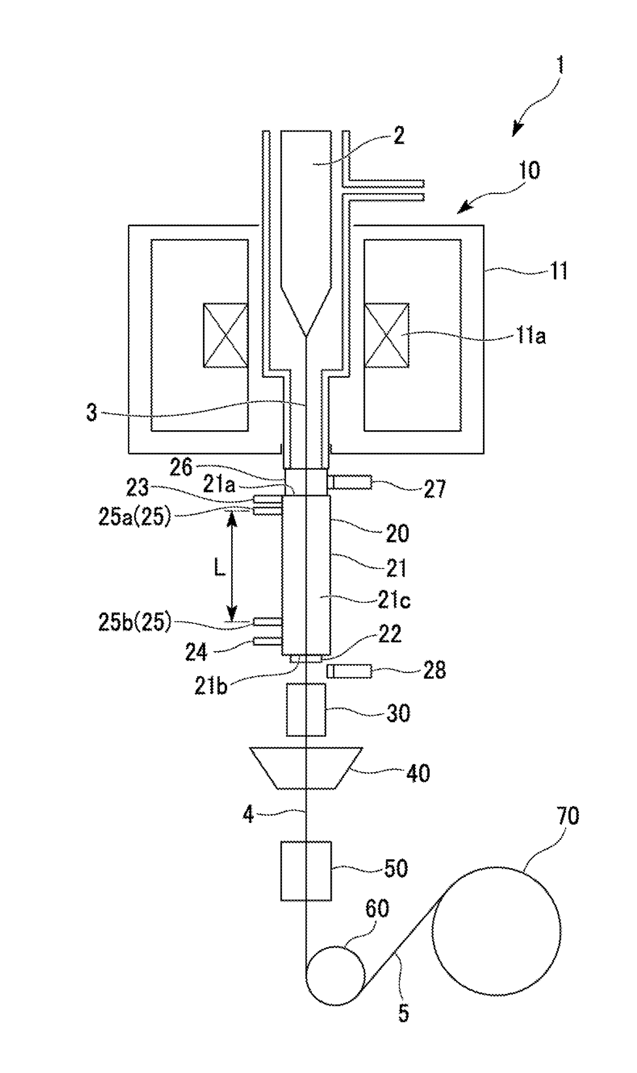
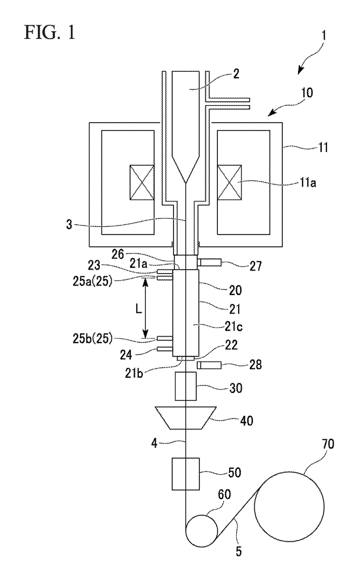
[0136]The optical fiber 5 was manufactured using the manufacturing apparatus shown in FIG. 1.

[0137]The total length of the slow-cooling device 20 was set to 3 m. The inner diameter of the main body 21 was set to 38.7 mm. The inside of the slow-cooling device 20 (the main body 21) was filled with Ar.

[0138]The fiber drawing velocity was set to 2,200 m / min. The temperature of the glass fiber 3 immediately before entering the slow-cooling device 20 was set to approximately 1,400° C. The inner wall temperature of the main body 21 of the slow-cooling device 20 was set to 1,000° C.

[0139]The flow rate of Ar introduced from the gas inlet / outlet portions 23 and 24 and the inner diameter of the opening of the constrictor 22 were adjusted so that a pressure change in the axial direction of the slow-cooling device 20 was approximately 4.5 Pa / m.

[0140]The result of the measurement by the radiation thermometer 28 was that the temperature of the glass fiber 3 at the outlet of the slow-cooling device...

example 2

[0142]The optical fiber 5 was manufactured using the manufacturing apparatus shown in FIG. 1.

[0143]The total length of the slow-cooling device 20 was set to 3 m. The inner diameter of the main body 21 of the slow-cooling device 20 was set to 20 mm. The inside of the slow-cooling device 20 (the main body 21) was filled with Ar.

[0144]The fiber drawing velocity was set to 2,200 m / min. The temperature of the glass fiber 3 immediately before entering the slow-cooling device 20 was set to approximately 1,400° C. The inner wall temperature of the main body 21 of the slow-cooling device 20 was set to 1,000° C.

[0145]The flow rate of Ar introduced from the gas inlet / outlet portions 23 and 24 and the inner diameter of the opening of the constrictor 22 were adjusted so that a pressure change in the axial direction of the slow-cooling device 20 was approximately 20 Pa / m. The other conditions were determined in accordance with Example 1.

[0146]The result of the measurement by the radiation thermom...

example 3

[0148]The optical fiber 5 was manufactured using the manufacturing apparatus shown in FIG. 1.

[0149]The total length of the slow-cooling device 20 was set to 3 m. The inner diameter of the main body 21 of the slow-cooling device 20 was set to 50 mm. The inside of the slow-cooling device 20 (the main body 21) was filled with Ar.

[0150]The fiber drawing velocity was set to 2,200 m / min. The temperature of the glass fiber 3 immediately before entering the slow-cooling device 20 was set to approximately 1,400° C. The inner wall temperature of the main body 21 of the slow-cooling device 20 was set to 1,000° C.

[0151]The flow rate of Ar introduced from the gas inlet / outlet portions 23 and 24 and the inner diameter of the opening of the constrictor 22 were adjusted so that a pressure change in the axial direction of the slow-cooling device 20 was approximately 2.5 Pa / m. The other conditions were determined in accordance with Example 1.

[0152]The result of the measurement by the radiation thermo...


PUM

PropertyMeasurementUnit
Reynolds numberaaaaaaaaaa
inner diameteraaaaaaaaaa
velocityaaaaaaaaaa

Abstract

An optical fiber manufacturing method includes: melting and drawing an optical fiber preform to form a glass fiber; cooling the glass fiber while inserting the glass fiber into a tubular slow-cooling device from an inlet end toward an outlet end thereof, and lowering an inner wall temperature of the slow-cooling device below a temperature of the glass fiber and providing a pressure gradient in which a pressure increases in a direction from the inlet end toward the outlet end inside the slow-cooling device when cooling the glass fiber, wherein the average pressure change dP/dL in a moving direction of the glass fiber inside the slow-cooling device satisfies the following Formula (1) when the tube inner diameter of the slow-cooling device is defined as D [m] and the length of an internal space of the slow-cooling device in the moving direction of the glass fiber is defined as L [m].
D2/4)×dP/dL≦0.03  (1)

Description

TECHNICAL FIELD[0001]The present invention relates to a method of manufacturing an optical fiber.[0002]This application claims priority from Japanese Patent Application No. 2015-158823, filed on Aug. 11, 2015, the contents of which are incorporated herein by reference in their entirety.BACKGROUND ART[0003]An optical signal to noise ratio (OSNR) needs to be increased to increase an optical transmission distance and transmission speed. Therefore, an optical fiber is required to have low loss characteristics.[0004]A silica core optical fiber, whose core region is substantially formed of only pure silica glass, has no light scattering due to fluctuation of added GeO2 concentration compared to a germa-core optical fiber (an optical fiber doped with GeO2 in the core). Therefore, it is known to be an optical fiber with low loss.[0005]A demand for even lower loss is still high for both silica core optical fibers and germa-core optical fibers.[0006]Recently, technologies of manufacturing opt...

Claims


Application Information

Patent Timeline
Patent Type & Authority Applications(United States)
IPC IPC(8): C03B37/025
CPCC03B2205/72C03B37/0253C03B37/02718C03B2205/56Y02P40/57
Inventor IMASE, AKIHITO
Owner THE FUJIKURA CABLE WORKS LTD
Why Eureka
Try Eureka