
Self-propelled elevators and elevator brake systems

a self-propelled, elevator technology, applied in the field of elevators, can solve the problems of not being able to travel along, maintenance of cables, tripping hazards, etc., and achieve the effect of accurately and safely operating an elevator cab, increasing the safety level of the elevator cab, and safe distance between multiple elevator cabs in the same elevator sha

Active Publication Date: 2017-08-10
LAU KENNY WAI KEUNG
View PDF13 Cites 10 Cited by
  • Summary
  • Abstract
  • Description
  • Claims
  • Application Information

AI Technical Summary

Benefits of technology

The present invention is a self-propanged elevator system that can maintain its vertical position when traveling on a curved track or non-vertical / horizontal track. It uses sensors and programming to maintain a safe distance between multiple elevator cabs in the same elevator shaft and quickly stops when approaching a barrier. The elevator brake system includes control modules, electromechanical brakes, leveling sensors, and speed sensors, which monitors elevator cab speed and stops it if there is excessive speed or unintended movement. The method for synchronizing and controlling multiple motors in a multi-motor elevator system uses a vector drive and CPU system to accurately and safely operate the elevator cab.

Problems solved by technology

These elevators can travel vertically and horizontally, but are not designed to travel along a curved track or a track that is neither vertical nor horizontal because the elevator cab will not stay in a vertical position.
The disadvantages for these elevators are obvious, and include the requirement for a machine room or space in the shaft to locate the machineries, maintenance of the cables due to wear and tear, and tripping hazard due to re-leveling as a result of cables stretching or weight changing when passengers enter or exit the elevator.
The design of such elevators is limited, and typically involves up and down movement of a single elevator cab in a straight vertical elevator shaft.
Furthermore, these elevators cannot fit into elevator shaft that are built to be used for hydraulic elevators because of the space limitation.
For hydraulic elevators, they suffer from the disadvantages of slow speed, noisy operation and a relatively low height limit.
The hydraulic elevators may also pose environmental hazard when there is leakage of the hydraulic fluid.
Most of the current solutions will work on new elevator systems but may be difficult to be adapted to older and existing elevators.
However, all the methods mentioned above only indirectly stop the elevator cab, and they suffer from substantial shortcomings.
For example, if the hoist cable breaks, the elevator will fall, and all of the above-mentioned emergency brake systems will be useless.

Method used


Image

  • Self-propelled elevators and elevator brake systems
  • Self-propelled elevators and elevator brake systems
  • Self-propelled elevators and elevator brake systems

Examples


Embodiment Construction

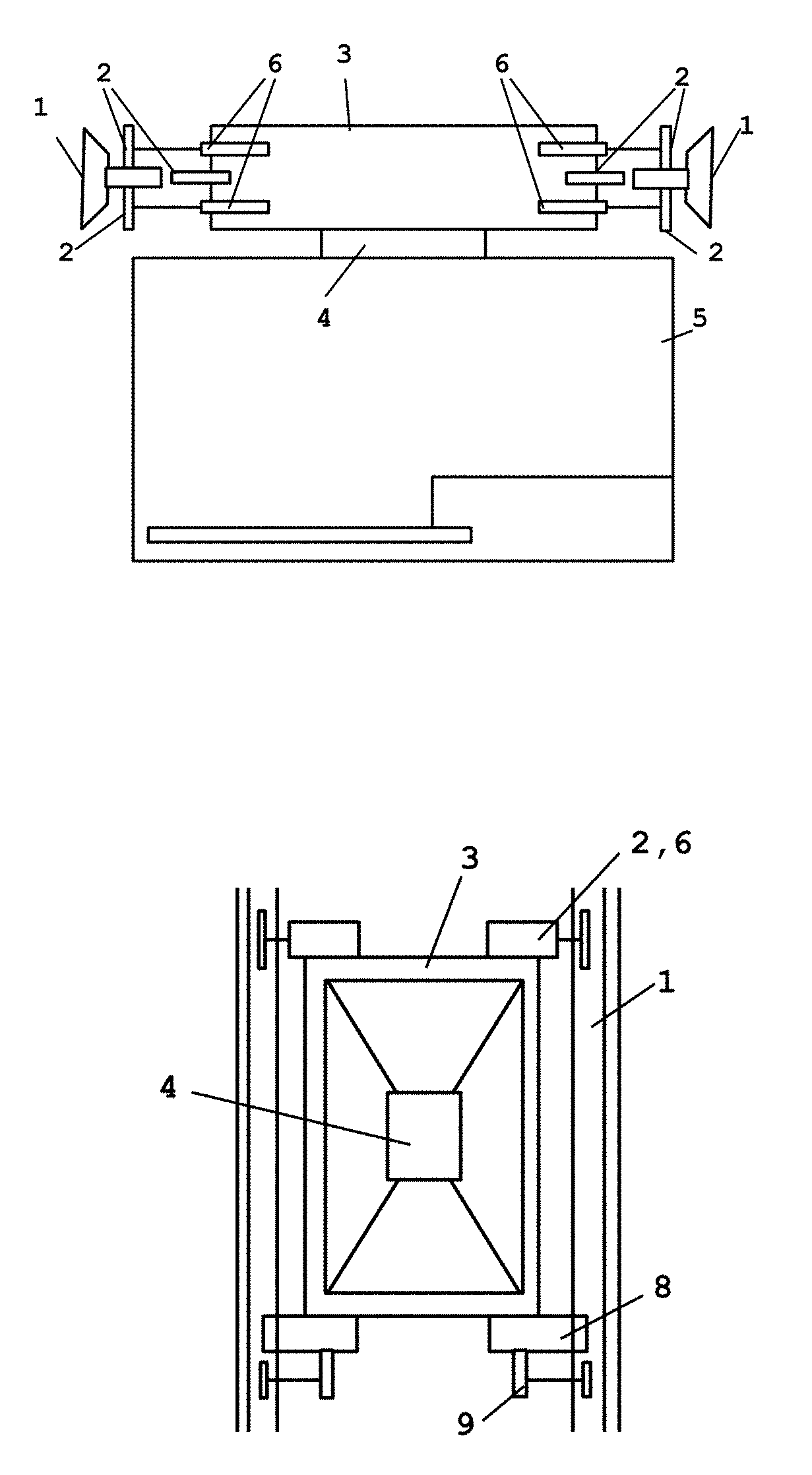
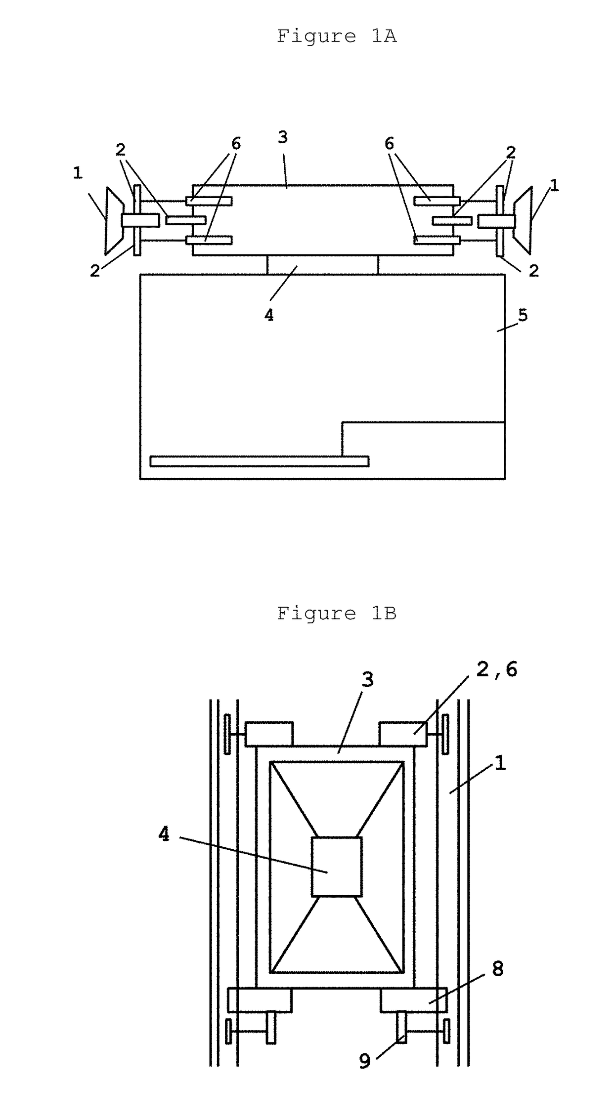
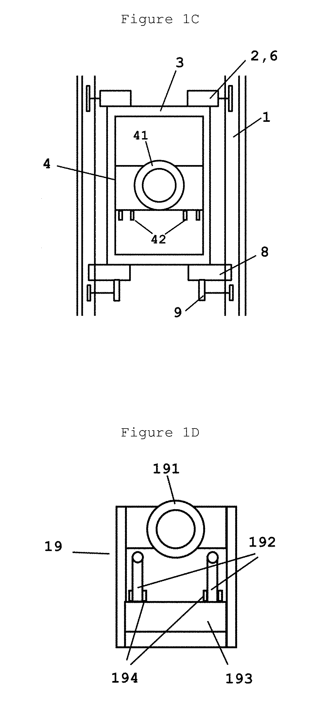
[0041]To overcome the deficiencies of existing elevator systems, the present invention provides a self-propelled elevator system having at least one motor, a method for synchronizing and controlling said multiple motors, and an elevator brake system that can be used not only in said self-propelled elevator system, but also in other types of elevators to increase the level of safety.

[0042]The self-propelled elevator of this invention has smaller elevator shaft and overhead space requirements than traction or machine room-less elevators, produces less noise, and does not need any machine room, hoist and governor cables, sheaves, governor, overheads, counterweights or rope gripper. Furthermore, the elevator of the present invention requires less installation time, does not need a temporary platform during installation, and requires no outside hoist when constructing a new building.

[0043]Advantages of the self-propelled elevator of this invention include:[0044]1) Since the motors are di...


PUM


Abstract

This invention is directed to a self-propelled elevator system having multiple motors or one motor, and methods for synchronizing said multiple motors. This invention is also directed to an elevator brake system to be used in said self-propelled elevator system or other types of elevators to increase their level of safety.

Description

FIELD OF THE INVENTION[0001]This invention relates to elevators, particularly self-propelled elevators, and elevator brake systems.BACKGROUND OF THE INVENTION[0002]Typically there is only one elevator per elevator shaft. In an attempt to save space and improve waiting time, some cableless elevators have been described, such as in U.S. Pat. Nos. 5,501,295, 4,051,923 and 3,658,155. These elevators can travel vertically and horizontally, but are not designed to travel along a curved track or a track that is neither vertical nor horizontal because the elevator cab will not stay in a vertical position.[0003]In current elevator systems, such as traction or machine room-less elevators, hoist cables above an elevator cab are used for pulling the cab up or down in a elevator shaft. The hoist cables are firmly connected to the elevator cab at one end and counter weights at the other. Machine sheave is turning to bring the elevator up and down. The disadvantages for these elevators are obvious...

Claims


Application Information

Patent Timeline
Patent Type & Authority Applications(United States)
IPC IPC(8): B66B5/18B66B11/02B66B1/36B66B5/04B66B11/04B66B5/00B66B1/30B66B1/40B66B9/02B66B1/32
CPCB66B5/18B66B9/02B66B11/02B66B1/36B66B1/32B66B5/04B66B11/0206B66B11/0286B66B5/0018B66B1/30B66B1/40B66B11/043B66B11/04B66D1/34B66D5/08B66B5/0031B66B5/06B66B7/00B66B9/003B66B9/06
Inventor LAU, KENNY WAI KEUNG
Owner LAU KENNY WAI KEUNG
Learn More