Aircraft brake and cooling methods therefor

a technology for aircraft brakes and cooling methods, which is applied in the field of cooling methods of aircraft brakes, can solve the problems of reducing the maximum temperature reached, reducing the size (and therefore the mass) of the brake pack, and reducing the temperature ris

Active Publication Date: 2017-08-10
AIRBUS OPERATIONS LTD
View PDF12 Cites 8 Cited by
  • Summary
  • Abstract
  • Description
  • Claims
  • Application Information

AI Technical Summary

Benefits of technology

[0009]The latent heat of vaporisation (hfg, also known as the enthalpy of vaporisation) represents the amount of energy needed to vaporise a unit mass of saturated liquid at a given temperature or pressure. Methods in accordance with the present invention may limit the temperature rise (i.e. cool) a brake pack by using some of the heat energy generated during the braking process to bring about a change in state of the coolant, rather than a rise in temperature of the brake. In cases where the size of the brake pack is dictated by the need to limit the temperature rise that occurs during a braking event, taking advantage of the latent heat of vaporisation may provide a way of reducing the size (and therefore the mass) of the brake pack.
[0010]The method may comprise the step of melting the coolant using heat energy from the brake pack. Thus, the method may also take advantage of the latent heat of fusion (hfus, also known as the enthalpy of fusion) as a means of absorbing heat energy during aircraft braking. The method may comprise the step of melting the coolant and then vaporising the coolant using heat energy from the brake pack. It will be appreciated that is some situations it may be advantageous to melt but not vaporise a coolant. The method may comprise a step of freezing a liquid coolant prior to braking, for example during flight, and then melting the coolant using heat energy from the brake pack.

Problems solved by technology

During braking a significant proportion of the kinetic energy of the aircraft is converted into heat energy that leads to a temperature rise in the brake pack.
However, the amount of heat such a system can remove from the brake pack during a relatively short braking event is limited and accordingly such system may have a limited impact on the maximum temperature reached during a braking event.
The use of such systems also increases the complexity of the brake assembly.

Method used


Image

  • Aircraft brake and cooling methods therefor
  • Aircraft brake and cooling methods therefor
  • Aircraft brake and cooling methods therefor

Examples


Embodiment Construction

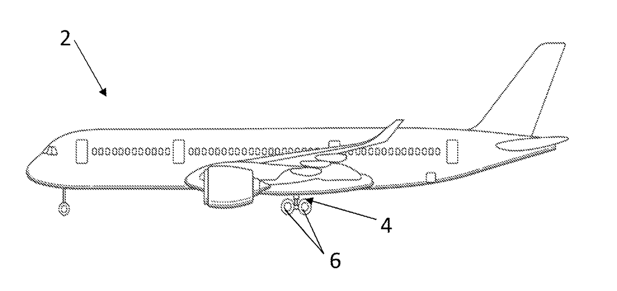
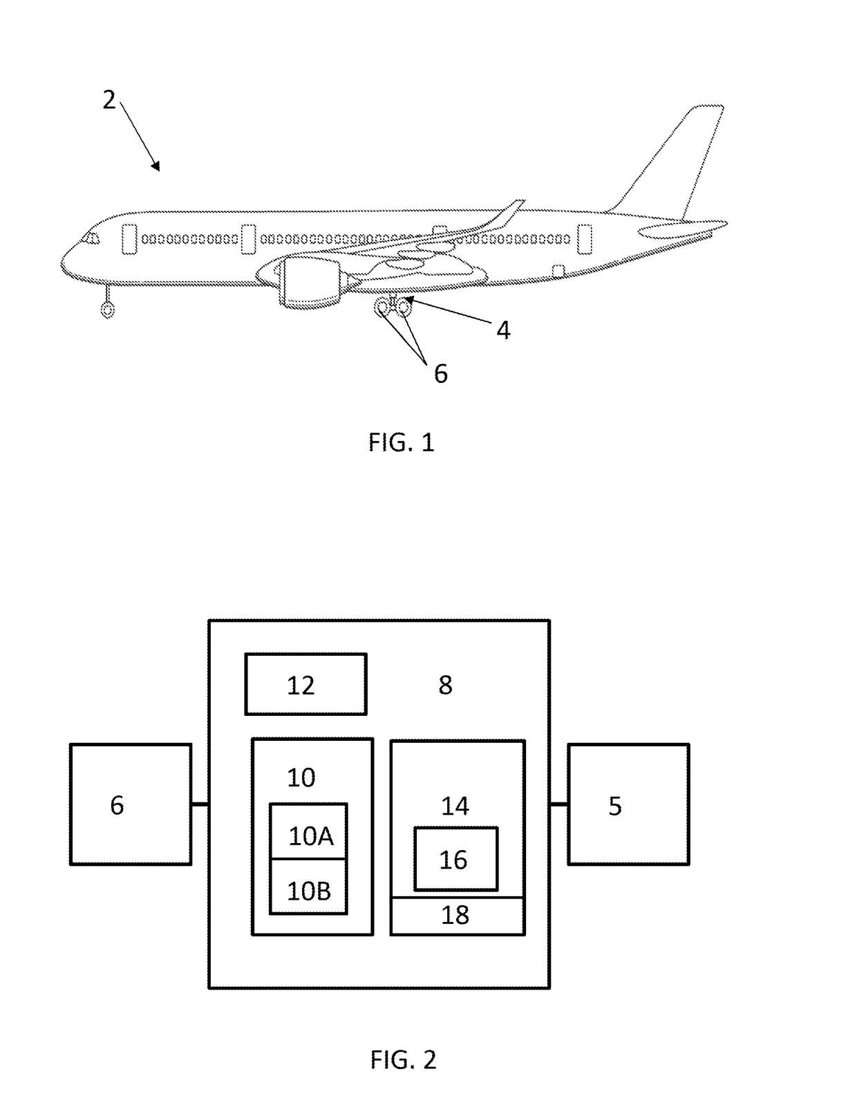
[0045]FIG. 1 shows an aircraft 2 having main landing gear 4, the main landing gear 4 including a landing gear bogie 5 and wheels 6. Each wheel 6 is associated with a brake 8 (not shown separately in FIG. 1). As shown schematically in FIG. 2, each brake 8 includes a brake pack 10 having several disk-like carbon stators 10a connected to the landing gear bogie 5 and several disk-like rotors 10b connected to the wheel 6, and a hydraulic system 12 arranged to move the stators 10a into contact with the rotors 10b in order to apply the brake 8. Also included in brake 8 is a cartridge 14 which is in contact with the inner rim of each stator 10a. Prior to use the cartridge 14 contains a quantity of distilled water 16. The cartridge 14 also includes a bung 18.

[0046]In use, when the brakes are applied heat is generated within the brake pack 10 due to friction between the rotors 10a and stators 10b. A portion of this heat energy is transferred to the cartridge 14 and from there to the water 16 ...


PUM


Abstract

A method of cooling an aircraft brake including a brake pack and a reservoir in the form of a removable cartridge containing a coolant. The method includes vaporizing the coolant using heat energy from the brake pack.

Description

BACKGROUND OF THE INVENTION[0001]The present invention concerns brakes for use on aircraft landing gear. More particularly, but not exclusively, this invention concerns methods of cooling an aircraft brake, particularly the brake pack. The invention also concerns an aircraft brake for use in such methods, a cartridge for use in such a brake and an aircraft landing gear and an aircraft including such brakes.[0002]Modern aircraft, particularly large aircraft, often use hydraulically actuated disc-type brakes on the landing gear. A typical aircraft brake may comprise a brake pack (also known as a heat pack) comprising a plurality of rotors (connected to the moving wheel) and a plurality of stators (connected to the landing gear bogies via a common piston), and a hydraulic system arranged to move the stators into contact with the rotors when a braking command is received. During braking a significant proportion of the kinetic energy of the aircraft is converted into heat energy that lea...

Claims


Application Information

Patent Timeline
Patent Type & Authority Applications(United States)
IPC IPC(8): F16D65/853B64C25/42
CPCF16D65/853B64C25/42F16D2121/02F16D2065/783F16D2200/0052F16D2065/781F16D65/84
Inventor GRAZEBROOK, ALVERY NOELFROST, NEIL
Owner AIRBUS OPERATIONS LTD
Why Eureka
Try Eureka