Vacuum heat-insulating material, and heat-insulating container, dwelling wall, transport machine, hydrogen transport tanker, and LNG transport tanker equipped with vacuum heat-insulating material

a technology of vacuum heat insulation and heat insulation container, which is applied in the direction of heat insulation, transportation and packaging, mechanical equipment, etc., can solve the problems of difficult to maintain a substantially vacuum state (closed and decompressed state) on the inside and the properties of vacuum heat insulation material are strict, so as to achieve the effect of optimizing the reliability of the outer cover material

Inactive Publication Date: 2017-08-17
PANASONIC INTELLECTUAL PROPERTY MANAGEMENT CO LTD
View PDF0 Cites 3 Cited by
  • Summary
  • Abstract
  • Description
  • Claims
  • Application Information

AI Technical Summary

Benefits of technology

[0016]According to the present invention, in the vacuum heat-insulating material, it is possible to further optimize reliabi

Problems solved by technology

When the outer cover material is damaged, the gas barrier properties of the vacuum heat-insulating material are lost or deteriorate, and thus, it becomes difficult to maintain a substantially vacuum state (tightly closed and decompressed state) on the inside of the vacuum heat-insulating material.
However, in the industrial product, compared to the consumer product, there is a tendency that requiring properties of the vacuum heat-insulating material are strict.
However, in the related art, i

Method used


Image

  • Vacuum heat-insulating material, and heat-insulating container, dwelling wall, transport machine, hydrogen transport tanker, and LNG transport tanker equipped with vacuum heat-insulating material
  • Vacuum heat-insulating material, and heat-insulating container, dwelling wall, transport machine, hydrogen transport tanker, and LNG transport tanker equipped with vacuum heat-insulating material
  • Vacuum heat-insulating material, and heat-insulating container, dwelling wall, transport machine, hydrogen transport tanker, and LNG transport tanker equipped with vacuum heat-insulating material

Examples


first exemplary embodiment

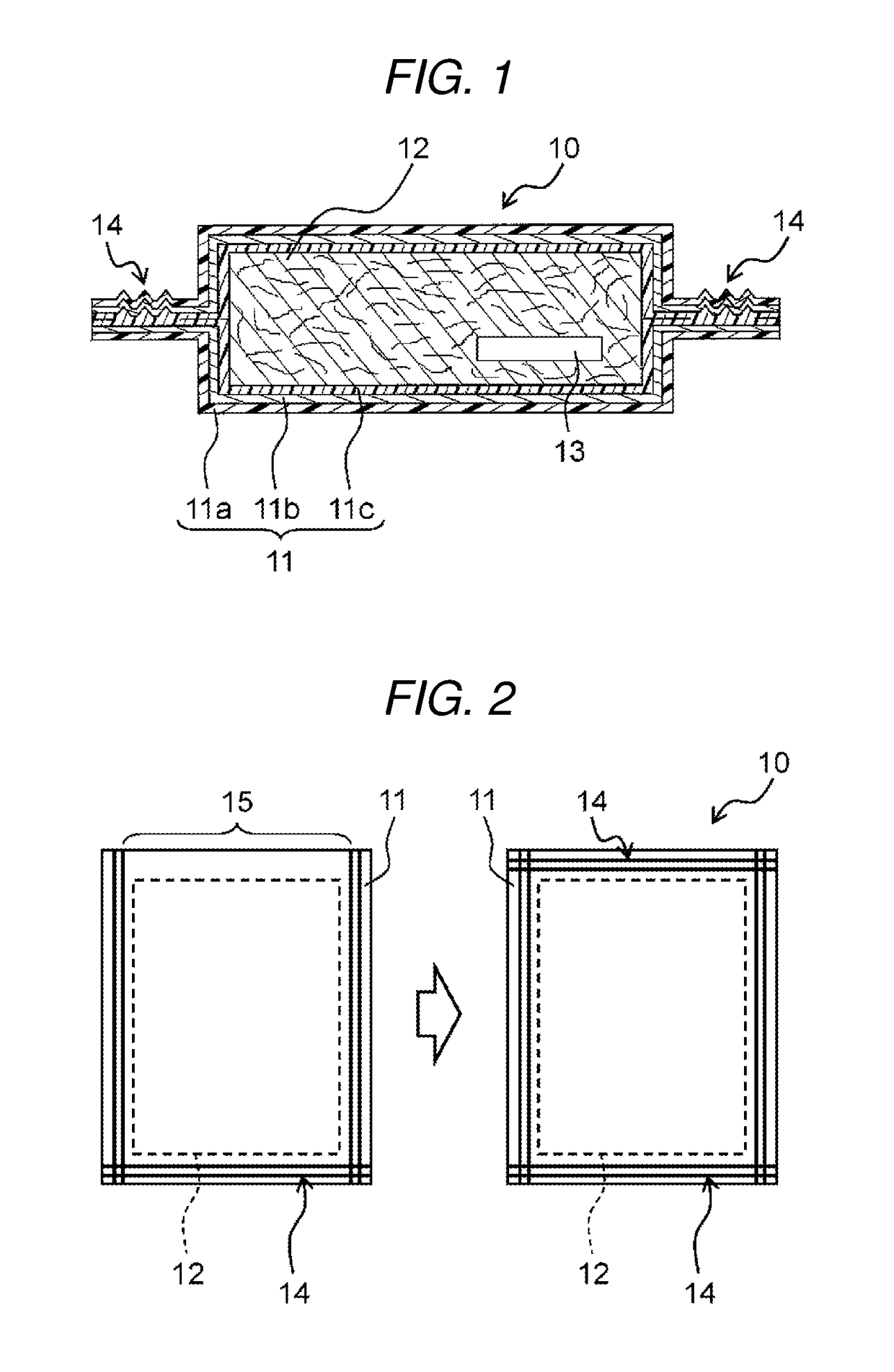
[0032]First, vacuum heat-insulating material 10 according to a first exemplary embodiment of the present invention will be described.

[Basic Configuration of Vacuum Heat-Insulating Material]

[0033]As illustrated in FIG. 1, vacuum heat-insulating material 10 according to the exemplary embodiment includes outer cover material 11 which is an outer package material and an inner member which is sealed in a tightly closed and decompressed state (substantially vacuum state) on the inside of outer cover material 11. The inner member is configured of a material which does not cause a chemical reaction which follows hydrogen when outer cover material 11 is ruptured (damaged or the like), water of liquid enters the inside, and outer cover material 11 comes into contact with the moisture. In vacuum heat-insulating material 10 according to the exemplary embodiment, core material 12 and adsorbent 13 are provided as the inner member.

[0034]Outer cover material 11 which is used in vacuum heat-insulati...

second exemplary embodiment

[0079]Next, a second exemplary embodiment of the present invention will be described.

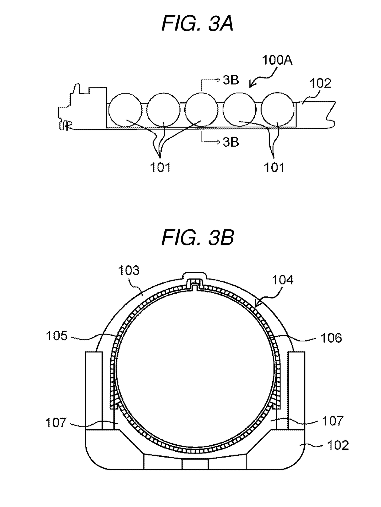
[0080]In the above-described first exemplary embodiment, a basic configuration example of vacuum heat-insulating material 10 according to the disclosure will be described, but in the second exemplary embodiment, as a specific example of the heat-insulating container equipped with vacuum heat-insulating material 10 according to the disclosure, LNG spherical tank 101 which is provided in LNG transport tanker 100A illustrated in FIG. 3A will be described.

[0081]As illustrated in FIG. 3A, LNG transport tanker 100A in the exemplary embodiment is a spherical independent tank type tanker and is provided with the plurality (five in total in FIG. 3A) of spherical tanks 101. The plurality of spherical tanks 101 are arranged in one row along the longitudinal direction of ship body 102. As illustrated in FIG. 3B, each of spherical tanks 101 is provided with container main body 104. The inside of container main b...

third exemplary embodiment

[0086]Next, a third exemplary embodiment will be described.

[0087]In the second exemplary embodiment, as a representative example of the heat-insulating container provided with vacuum heat-insulating material 10 according to the disclosure, spherical tank 101 provided in LNG transport tanker 100A as illustrated in FIGS. 3A and 3B is illustrated as an example, but the present invention is not limited thereto.

[0088]In the third exemplary embodiment, as the heat-insulating container provided with vacuum heat-insulating material 10 according to the disclosure, as illustrated in FIGS. 4A and 4B, LNG inboard tank 110 provided with membrane type LNG transport tanker 100B will be described as an example.

[0089]As illustrated in FIG. 4A, LNG transport tanker 100B in the exemplary embodiment is a membrane type tanker, and is provided with the plurality of inboard tanks 110 (four in total in FIG. 4A). The plurality of inboard tanks 110 are arranged in one row along the longitudinal direction of ...


PUM


Abstract

A vacuum heat-insulating material includes: an outer cover material; and a core material which is sealed in a tightly closed and decompressed state on the inside of the outer cover material. Outer cover material has gas barrier properties and satisfies at least one of a condition that a linear expansion coefficient is 80×10−5/° C. or lower when a static load is 0.05 N within a temperature range of −130° C. to 80° C., inclusive, a condition that an average value of a linear expansion coefficient is 65×10−5/° C. or higher when a static load is 0.4 N within a temperature range of −140° C. to −130° C., inclusive, a condition that an average value of a linear expansion coefficient is 20×10−5/° C. or higher when a static load is 0.4 N within a temperature range of −140° C. to −110° C., inclusive, and a condition that an average value of a linear expansion coefficient is 13×10−5/° C. or higher when a static load is 0.4 N within a temperature range of +50° C. to +65° C., inclusive.

Description

TECHNICAL FIELD[0001]The present invention relates to a vacuum heat-insulating material having a configuration in which a core material is sealed in a tightly closed and decompressed state on the inside of an outer cover material, and a heat-insulating container, a dwelling wall, a transport machine, a hydrogen transport tanker, and an LNG transport tanker equipped with the vacuum heat-insulating material.BACKGROUND ART[0002]A vacuum heat-insulating material has a configuration in which a core material is tightly closed and decompressed and sealed on the inside of an outer cover material (outer package material) having gas barrier properties. As the outer cover material, generally, a laminated film on which functional layers, such as a thermal welding layer, a front surface protecting layer, and a gas barrier layer, are laminated is used.[0003]The vacuum heat-insulating material is widely used in consumer products, such as electric appliances or housing materials, but in recent year...

Claims


Application Information

Patent Timeline
IPC IPC(8): F17C3/08F17C3/04E04B1/80B63B25/16E04B1/76
CPCF17C3/08B63B25/16E04B1/7612E04B1/803E04B1/806F17C2270/0171F17C2221/033F17C2221/012F17C2203/0636F17C2203/0391F17C3/04F17C1/12F17C2270/0105F17C2203/0634F16L59/065Y02A30/242Y02B80/10Y02E60/32F16L59/07F17C2201/052F17C2201/0123F17C2201/0157F17C2223/0161F17C2223/033F17C2270/0107F17C2270/0134F17C2270/0142F17C2201/0109F17C2201/0128F17C2201/032F17C2205/018F17C2203/0678E04B1/80
Inventor SHIMA, MICHIHIROYUASA, AKIKO
Owner PANASONIC INTELLECTUAL PROPERTY MANAGEMENT CO LTD
Why Eureka
Try Eureka