Burst optical signal transmission device and burst optical signal transmission method

a transmission device and optical signal technology, applied in optical transmission, electromagnetic transmission, semiconductor lasers, etc., can solve the problems of inability to obtain practical systems and significant cost increases of transceivers, and achieve the effects of not causing transmission errors, fast burst rising time, and less distortion of optical signal waveforms

Active Publication Date: 2017-08-17
NIPPON TELEGRAPH & TELEPHONE CORP
View PDF3 Cites 10 Cited by
  • Summary
  • Abstract
  • Description
  • Claims
  • Application Information

AI Technical Summary

Benefits of technology

[0033]As described above, with use of the technique of the present invention, external modulator type burst optical signal transmission with a fast burst rising time that can perform, even in the C-band, long-distance transmission of 20 km or more that has less distortion of an optical signal waveform caused by wavelength dispersion, and does not cause a transmission error even at a burst signal transmission start can be realized.

Problems solved by technology

On the other hand, it is considered that capacity enlargement exceeding the 10 Gb / s level is required depending on the services such as a high-definition video service, but further speedup (40 or 100 Gb / s level) in bit rate of a transceiver involves a significant cost increase of the transceiver, and a practical system cannot be obtained, which has been a problem.

Method used


Image

  • Burst optical signal transmission device and burst optical signal transmission method
  • Burst optical signal transmission device and burst optical signal transmission method
  • Burst optical signal transmission device and burst optical signal transmission method

Examples


first embodiment

of Invention

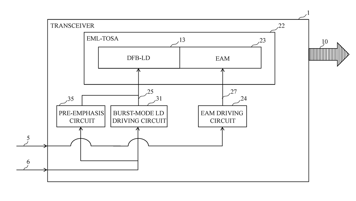
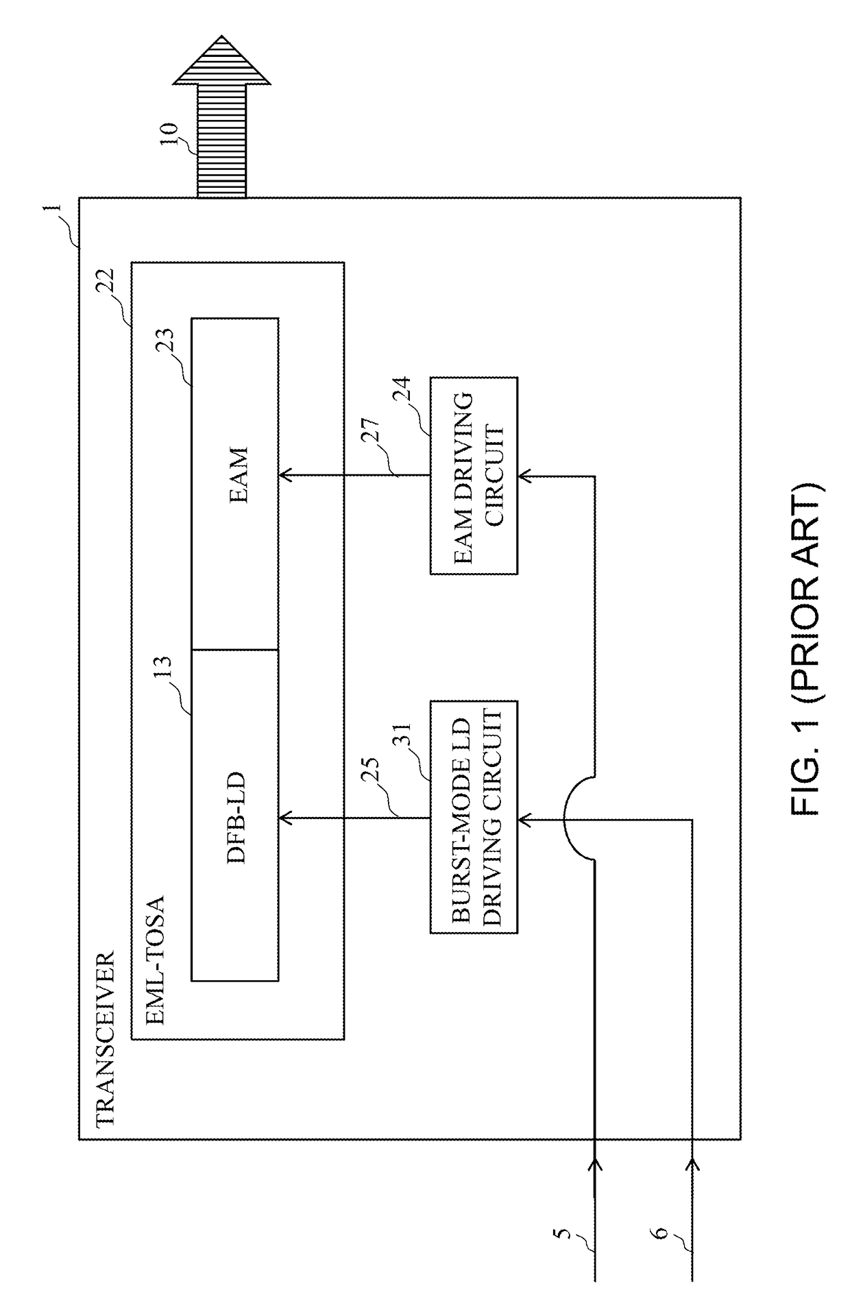
[0048]A control method for a 10 Gb / s level external modulator type burst optical signal transmitter according to a first embodiment of the present invention will be described in detail below based on FIGS. 6 to 8. FIG. 6 illustrates a configuration of a transceiver 1 in the 10 Gb / s level external modulator type burst signal optical transmitter being the first embodiment of the present invention. The transceiver 1 outputting burst signal light 10 includes an EML-TOSA 22, an EAM driving circuit 24, a burst-mode LD driving circuit 31, and a pre-emphasis circuit 35, and the EML-TOSA 22 includes a DFB-LD 13 and an EAM 23. Here, the transceiver 1 may function as a burst optical signal transmission device, the burst-mode LD driving circuit 31 may function as a light source driving circuit, and the DFB-LD 13 may function as a light source.

[0049]Transmission signal data 5 input from the outside is received by the EAM driving circuit 24, and output to the EAM 23 via an EAM signal ...

second embodiment

of Invention

[0069]A control method for a 10 Gb / s level external modulator type burst optical signal transmitter being a second embodiment of the present invention will be described in detail below based on FIGS. 6 to 7, and 9. FIG. 6 illustrates a configuration of the 10 Gb / s level external modulator type burst signal optical transmitter being the second embodiment of the present invention, and illustration is given while focusing attention only on a transmission unit of a transceiver 1 equipped in an GNU (receiver unit and other peripheral circuits are omitted).

[0070]In addition, FIG. 7 illustrates a burst control circuit in the present embodiment, and FIG. 9 illustrates a time chart in the present embodiment. In FIG. 6, the transmission unit mainly includes the EML-TOSA 22 including the EML (the DFB-LD 13 and the EAM 23), the burst-mode LD driving circuit 31, the pre-emphasis circuit 35, and the EAM driving circuit 24.

[0071]Burst signal light 10 transmitted from the transceiver 1 ...

third embodiment

of Invention

[0077]A burst optical signal transmission device according to the present embodiment further includes a current supplying unit (not illustrated) for further shortening a charging time tchg. The current supplying unit (not illustrated) may be included in a burst-mode LD driving circuit 31 or a pre-emphasis circuit 35.

[0078]The current supplying unit (not illustrated) supplies, to a DFB-LD 13, such arbitrary current as to fall within a range being smaller than a second predetermined rate being lower than the first predetermined rate of the load capability Cp that has been described in the first embodiment of the present invention. For example, the second predetermined rate of the load capability Cp is an arbitrary rate being, for example, equal to or larger than 0% and smaller than 50%.

[0079]The current to be supplied by the current supplying unit (not illustrated) is preferably current with such an extent that the DFB-LD 13 does not emit light. Thus, the second predetermi...


PUM


Abstract

A burst optical signal transmission device which includes a light source for generating and outputting burst signal light, a light source driving circuit for outputting, to the light source, a driving signal for switching between an output time and a stop time of the burst signal light, based on a burst control signal, and a pre-emphasis circuit for outputting a pre-emphasis control signal for superimposing an additional signal for charging a capacitor included in the light source, onto the driving signal, at a timing in the vicinity of the beginning of the burst control signal.

Description

TECHNICAL FIELD[0001]The present invention relates to a burst optical signal transmission device for transmitting a burst optical signal, and a control method for the same.BACKGROUND ART[0002]In recent years, along with the rapid popularization of the Internet, the capacity enlargement, more advanced functions, and economization of an optical access system have been demanded. As a method for realizing such a system, the research of a passive optical network (PON) has been advanced. The PON is an optical access communication system advantageous for economization because it can share a transmission path between an equipment at a central office and an optical components at the user's premises by using passive element, such as optical power splitter.[0003]In Japan, there has been currently introduced an economic optical access communication system GE-PON (Gigabit Ethernet (registered trademark)-PON) that shares a throughput of 1 Gb / s level among up to 32 users, by time division multiple...

Claims


Application Information

Patent Timeline
Patent Type & Authority Applications(United States)
IPC IPC(8): H01S5/042H04B10/50H01S5/12
CPCH04B10/503H01S5/042H01S5/0085H01S5/0427H01S5/06213H01S5/06216H01S5/12H04B10/25137H04B10/541H04B2210/254
Inventor ASAKA, KOTATAGUCHI, KATSUHISA
Owner NIPPON TELEGRAPH & TELEPHONE CORP
Why Eureka
Try Eureka