Longwave infrared imaging of a high-temperature, high-intensity light source

a high-intensity, light source technology, applied in the field of electromagnetic imaging, can solve the problems of high equipment cost, inability to achieve complete imaging of the weld, and significant degradation of the overall image quality of conventional approaches, so as to reduce the intensity of electromagnetic radiation, reduce the saturation of the focal plane array of the lwir camera, and reduce the overall radiance sensitivity

Active Publication Date: 2016-04-05
THE UNITED STATES OF AMERICA AS REPRESENTED BY THE SECRETARY OF THE NAVY
View PDF13 Cites 1 Cited by
  • Summary
  • Abstract
  • Description
  • Claims
  • Application Information

AI Technical Summary

Benefits of technology

[0020]Exemplary inventive practice implements a controllable uncooled longwave (e.g., operable in the wavelength λ range of approximately 7.5 μm-14 μm, inclusive) IR camera in conjunction with a neutral density (ND) filter. The present inventors obtained successful test results using a thin transparent polystyrene window as the ND filter. The clear plastic polystyrene pane reduced the intensity of the electromagnetic radiation emanating from the arc weld, and thereby reduced the saturation of the LWIR camera's focal plane array by the LWIR radiation included in the electromagnetic radiation. The controllable uncooled longwave IR camera served to reduce overall radiance sensitivity, as compared with other types of cameras. The thin transparent polystyrene window served to reduce the welding arc IR radiation saturation of the IR camera's focal plane array.
[0021]The present invention's performance of weld pool / welding arc imaging / monitoring using attenuated LWIR to create images is previously unknown. Typically, as compared with a cooled midwave IR camera, an uncooled LWIR camera has significantly less overall sensitivity to thermal radiance. Therefore, in combination with an uncooled LWIR camera, a relatively moderate amount of filtering will be necessary to attenuate the thermal energy emanating from the object being imaged. Accordingly, the present invention represents an elegant solution whereby an infrared camera that is less prone to saturation is used concomitantly with a neutral density filter that is less prone to thermal overheating and optical distortion.

Problems solved by technology

However, conventional approaches can suffer significant degradation of the overall image quality.
Rejection by filters of specific wavelengths of light can be detrimental to complete imaging of the weld pool and welding arc.
Camera systems that use external laser lighting to suppress specific arc radiation wavelengths have practical drawbacks such as high equipment costs, occupational safety issues associated with high power lasers, and system integration challenges; these drawbacks have largely relegated the use of external lighting welding arc imaging to research applications.
However, UDR photography delays image broadcast and decreases video frame rate, resulting in “jumpy” video that ostensibly is real-time but actually is less than real-time.
UDR photography algorithms attempt to correct for this, but none are proficient at doing so; they tend to create choppy images due to decreased video frame rates.
Band-pass filtering of the arc light has been performed to improve the quality of the near-weld pool data; however, the radiance of the arc radiance, and the reflection of arc light off the surface of the weld pool, create noise that reduces quality of the image.
Due in part to the difficulty of resolving the significant amount of IR interference caused by the intense, complex radiation of welding arcs, early researchers focused their attention on near-weld pool thermography rather than on weld pool or arc imaging.
Moreover, the dramatic thermal gradients existing between welding arcs and surrounding material, coupled with IR detector limits of the time, further confounded both IR data and resulting imagery.

Method used


Image

  • Longwave infrared imaging of a high-temperature, high-intensity light source
  • Longwave infrared imaging of a high-temperature, high-intensity light source
  • Longwave infrared imaging of a high-temperature, high-intensity light source

Examples


Embodiment Construction

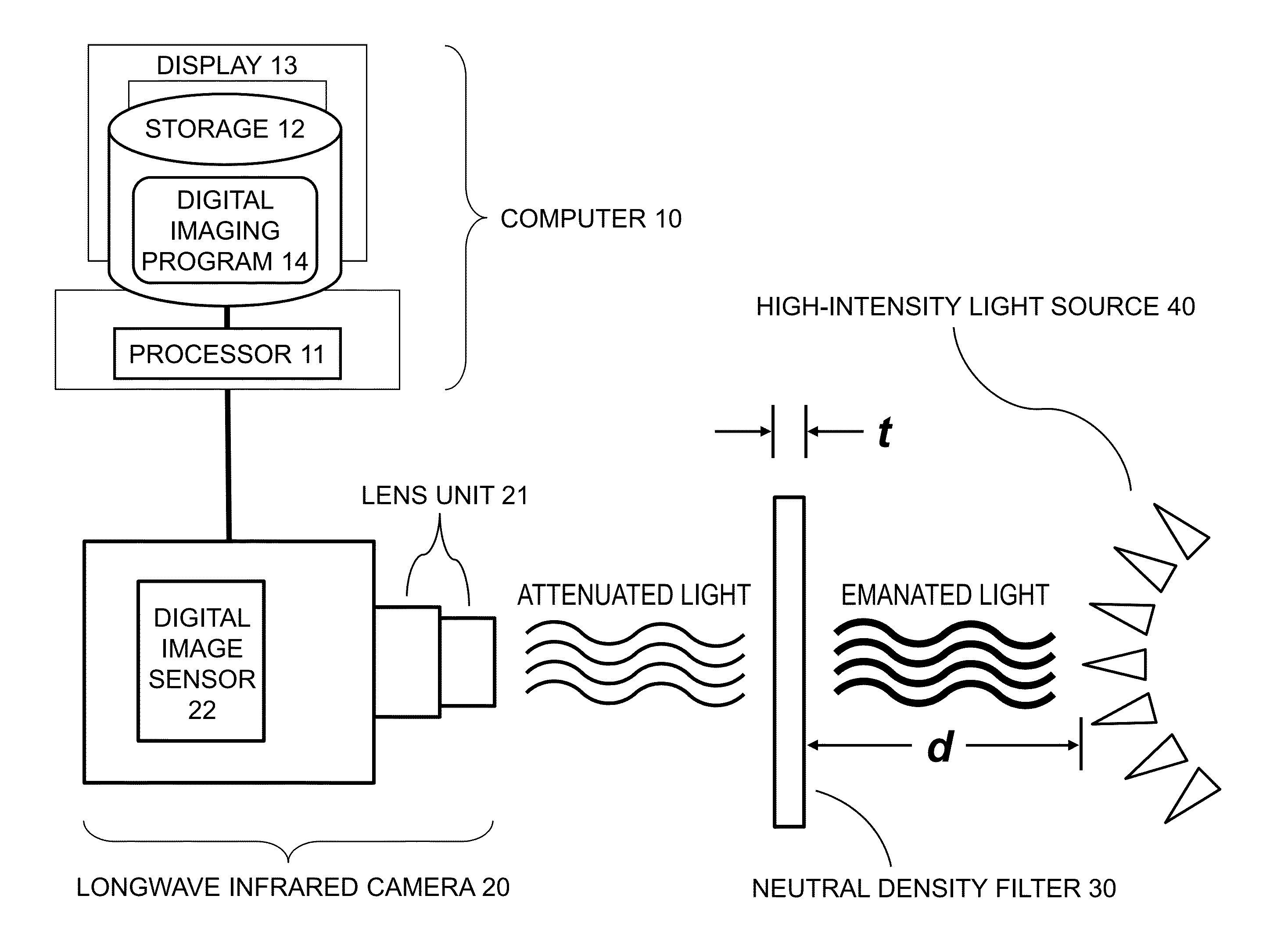
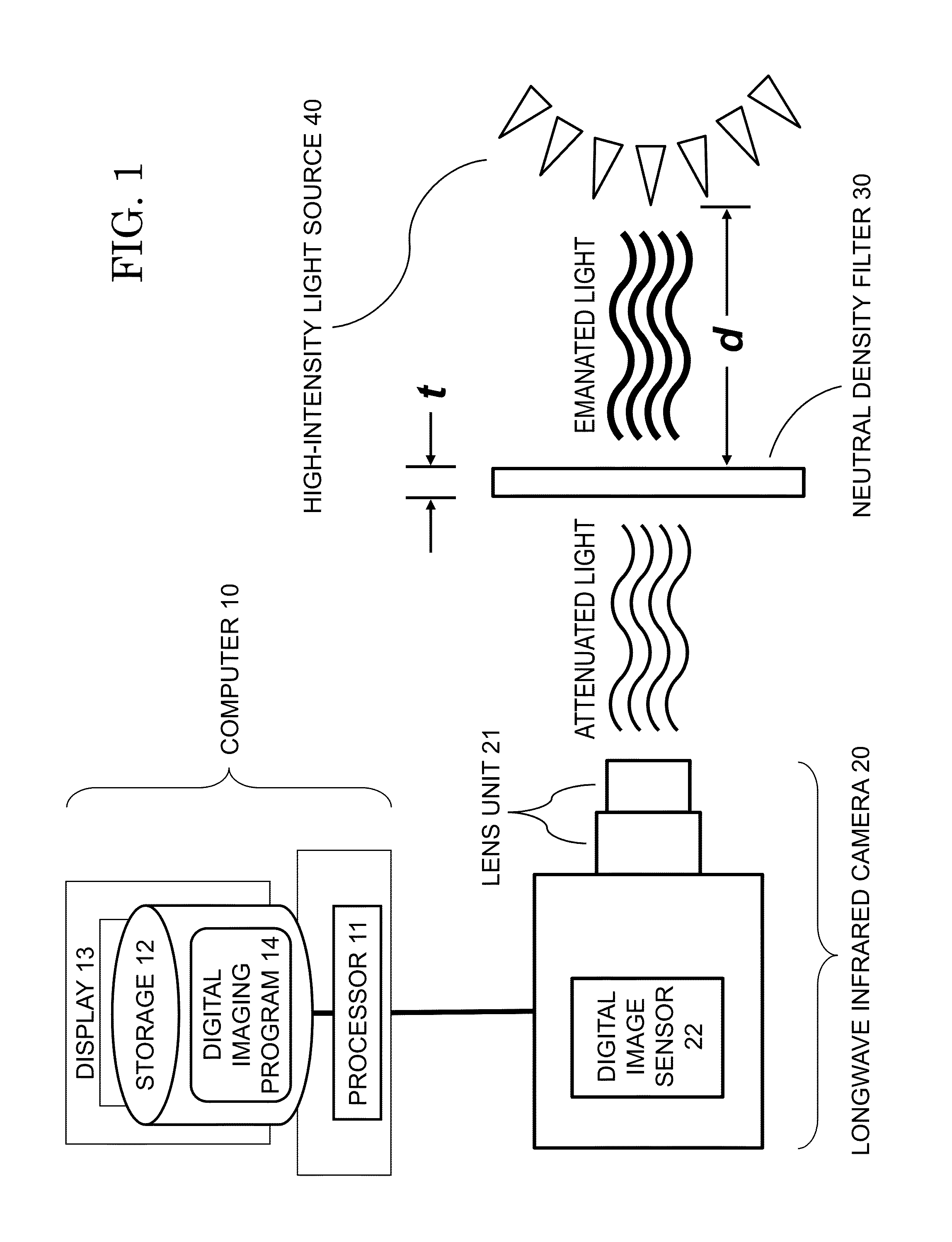
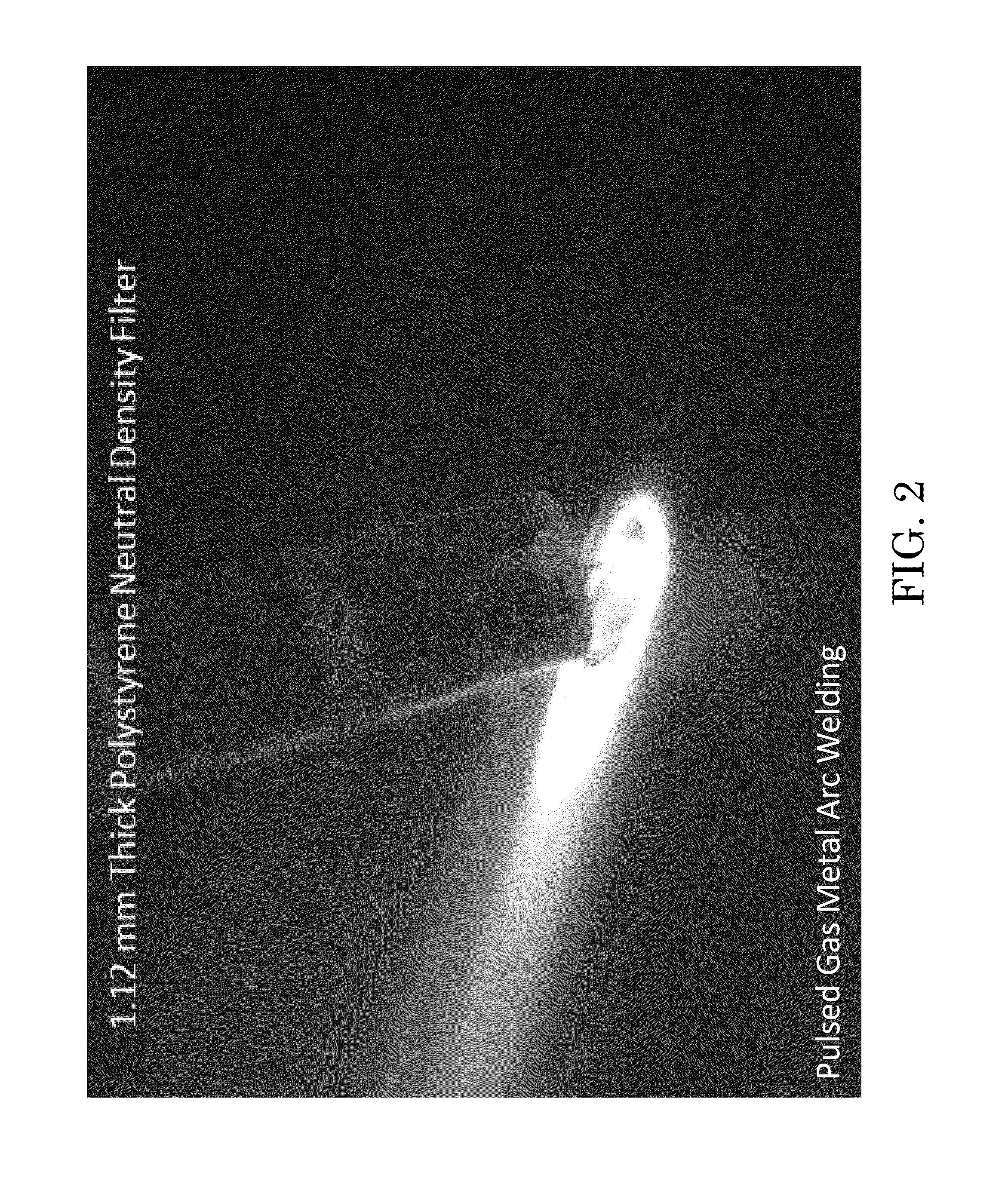
[0032]Referring now to the figures, according to exemplary practice of the present invention, thermal imaging is conducted of an arc welding process. As illustrated in FIG. 1, an exemplary inventive configuration for imaging a high temperature, high-intensity light source 40 includes a computer system 10, a longwave infrared (LWIR) camera / imager 20, and a neutral density (ND) filter 30. FIG. 1 is diagrammatic in nature and is not intended to convey spatial or dimensional preferences.

[0033]Computer system 10 includes a processor 11, a memory / storage 12 (both volatile and non-volatile), and a display 13. Neutral density (ND) filter 30 has a thickness t and is situated between a longwave infrared camera 20 and a light source 40 (such as an arc welding process). ND filter 30 is situated at a distance d from light source 40 and is nearer to camera 20 than to light source 40, according to exemplary inventive practice. LWIR camera 20, an uncooled thermal imaging camera, includes a lens uni...


PUM


Abstract

A neutral density (ND) filter made of an LWIR-transmissive, heat-resistant material is interposed between a longwave infrared (LWIR) imager and an entity that is highly emanative of both light and heat. According to exemplary inventive practice, the ND filter is a thermoplastic (e.g., polystyrene) sheet characterized by a thickness in the 1-2 mm range and a thermal conductivity≦0.13 W/m-K. Important parameters of the ND filter include LWIR transmittance (which depends on material and thickness) and thermal conductivity (which depends on material). The quality of the image taken of the entity is affected by the respective degrees of LWIR attenuation by, and heating up of, the ND filter. Accordingly, the material and the thickness of the ND filter are selected to optimize the image, in particular so as to avoid saturation and/or whiting-out of the image due to insufficient LWIR attenuation and/or excessive ND filter temperature.

Description

BACKGROUND OF THE INVENTION[0001]The present invention relates to electromagnetic imaging, more particularly to methods, systems, and computer programs for obtaining electromagnetic images of objects characterized by high-temperature, high-intensity light.[0002]Various electromagnetic spectral band regions—for instance, visible light, radio, infrared, x-rays, etc.—have been used to detect objects or obtain images of objects. Active detecting / imaging devices (e.g., radar devices) transmit electromagnetic radiation (e.g., radio signals) to detect or image objects. Passive detecting / imaging devices do not transmit electromagnetic radiation, but instead receive naturally occurring electromagnetic signals that are emitted or reflected by objects.[0003]In the electromagnetic spectrum, the infrared (IR) region is characterized by longer wavelengths than the visual region. The IR region extends between the visual region and approximately one millimeter in wavelength. The millimeter wave reg...

Claims


Application Information

Patent Timeline
Patent Type & Authority Patents(United States)
IPC IPC(8): H04N5/235
CPCH04N5/235H04N5/33G01J2005/0077G01J5/0018H04N23/75H04N23/70
Inventor SINFIELD, MATTHEWLUEKEN, DENNIS M.SETLIK, BRIAN J.
Owner THE UNITED STATES OF AMERICA AS REPRESENTED BY THE SECRETARY OF THE NAVY
Why Eureka
Try Eureka