Two-stage biomass pyrolysis

a biomass pyrolysis and two-stage technology, applied in the direction of biofuels, mechanical conveying coke ovens, horizontal chamber coke ovens, etc., can solve the problems of lowering efficiency and yield below commercially-viable levels, neither option is conducive to the design of a large, commercial-scale pyrolysis system, etc., to facilitate the pyrolysis of un-pyrolyzed biomass and facilitate the upgrading of the second condensable.

Active Publication Date: 2017-08-24
PHILLIPS 66 CO
View PDF0 Cites 8 Cited by
  • Summary
  • Abstract
  • Description
  • Claims
  • Application Information

AI Technical Summary

Benefits of technology

[0011]In certain embodiments, the second pyrolysis reactor comprises a bed containing at least one catalyst that facilitates pyrolysis of the un-pyrolyzed biomass, facilitates upgrading of the second condensable pyrolysis v

Problems solved by technology

A major barrier to commercial implementation of this pyrolysis technology for production of biofuels is that the condensable pyrolysis vapors include many highly-reactive intermediate compounds comprising radicals.
These compounds rapidly react to form secondary compounds that are difficult to upgrade to transportation fuels.
However, neither of these options is conducive to the design of a large, commercial-scale pyrolysis system.
Unfortunately, small volume reactors often lack sufficient residence time to completely pyrolyze the feedstock, thereby lowering efficiency and yield beneath commercially-viable levels.
Alternatively, increasing the throughput of sweep gas (or sweep gas rate) also decreases efficiency by: 1) excessively diluting the pyrolysis vapors, making subsequent catalytic upgrading less efficient, 2) requiring more energy to heat the larger volume of sweep gas, and 3) potentially increasing char entrainment in the p

Method used


Image

  • Two-stage biomass pyrolysis
  • Two-stage biomass pyrolysis
  • Two-stage biomass pyrolysis

Examples


Embodiment Construction

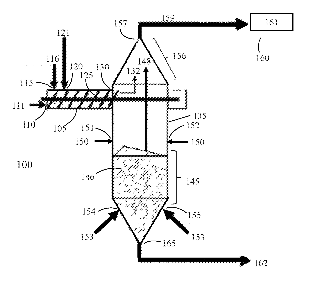
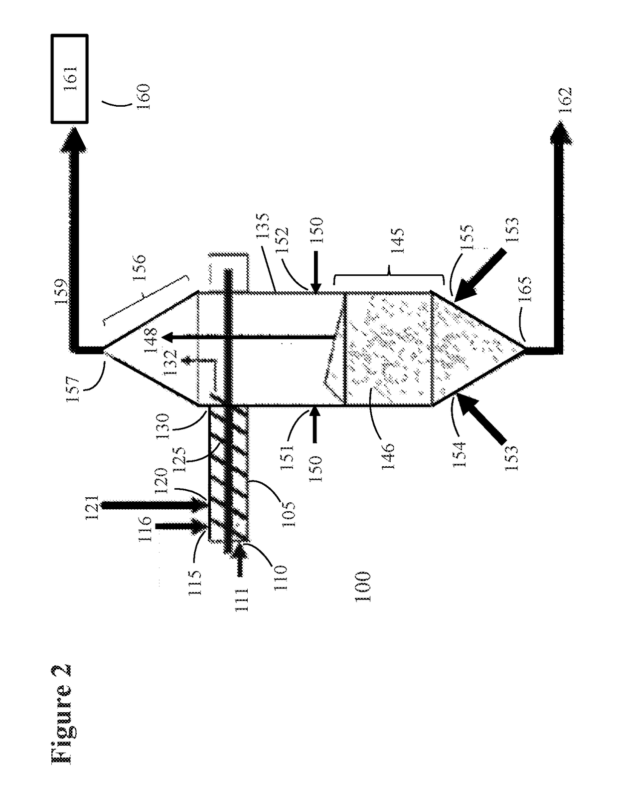
[0021]The inventive processes disclosed below partly relate to processes and systems for pyrolyzing a lignocellulosic biomass feedstock in a pyrolysis reactor comprising two reactor stages. The inventive processes and systems provide multiple pyrolysis residence times for more efficient pyrolysis of the different molecular components within a lignocellulosic feedstock. In certain embodiments, each reactor stage conducts pyrolysis at a different temperature to further maximize the efficiency of cellulosic biomass conversion into products that are suitable for use as a liquid hydrocarbon transportation fuel, fuel component, or mixtures thereof.

[0022]Examples of biomass feedstock used in the present invention include, but are not limited to lignocellulosic biomass, which is available from a variety of sources including forest residues, dead trees, branches, leaves, tree stumps, yard clippings, wood chips, wood fiber, sugar beets, miscanthus, switchgrass, hemp, corn, corn fiber, poplar,...


PUM


Abstract

The present disclosure relates generally to a two-stage biomass pyrolysis processes that maximize pyrolysis vapor yield from a lignocellulosic biomass while being conducive to commercial-scale throughput of biomass. A lignocellulosic feedstock is first pyrolyzed in a reactor first stage comprising at least one auger at a temperature and residence time that produces pyrolysis vapors derived predominantly from cellulose and hemi-cellulose fractions of the feedstock. Partially-pyrolyzed feedstock from the reactor first stage is then pyrolyzed in a reactor second stage at a higher temperature for an additional residence time to produce additional pyrolysis vapors that are predominantly derived from lignin. Certain embodiments arrange multiple reactor first stages around a single reactor second stage.

Description

CROSS-REFERENCE TO RELATED APPLICATIONS[0001]This application is a non-provisional application which according to 35 U.S.C. §119(e), claims the benefit of, and the right of priority to, U.S. Provisional Application Ser. No. 62 / 298,557 filed Feb. 23, 2016, entitled “Two-Stage Biomass Pyrolysis,” both of which are incorporated herein in their entirety, as permitted under 37 CFR 1.57(b).STATEMENT REGARDING FEDERALLY SPONSORED RESEARCH OR DEVELOPMENT[0002]None.FIELD OF THE INVENTION[0003]This invention relates to pyrolysis of organic matter into useful chemical or fuel products.BACKGROUND[0004]Conventional fast pyrolysis of biomass entails rapid heating of a biomass feedstock in a hypoxic environment to produce a combination of non-condensable gases (C1-C4), condensable pyrolysis vapors and solid carbonaceous char. Conventional fast pyrolysis of biomass typically mixes biomass with a heated solid particles (i.e., “heat carrier”) to facilitate rapid heating of the biomass to a temperatur...

Claims


Application Information

Patent Timeline
IPC IPC(8): C10B53/02C10B5/00C10B49/06C10B57/06C10B49/18C10B7/10C10B3/00
CPCC10B53/02C10B7/10C10B5/00C10B49/06C10B57/06C10B49/18C10B3/00C10B49/16Y02E50/10Y02P20/145
Inventor DALLUGE, DUSTIN L.LUSK, STEVEN E.JONES, SAMUEL T.GORKE, JOHNATHAN T.
Owner PHILLIPS 66 CO
Why Eureka
Try Eureka