
LED Driving System with Power Transmission Path Coincided with Data Transmission Path

a technology of power transmission path and led driving system, which is applied in the direction of electroluminescent light source, lighting apparatus, light source, etc., can solve the problems of increased thickness of fpc copper foil, increased cost of led products, etc., and achieves the reduction of fpc thickness, simplifying the wiring of the led driving system, and increasing the cost of products

Inactive Publication Date: 2017-09-07
DONGGUAN CITY MINLEON ELECTRONICS CO LTD
View PDF3 Cites 8 Cited by
  • Summary
  • Abstract
  • Description
  • Claims
  • Application Information

AI Technical Summary

Benefits of technology

The present invention aims to provide an LED driving system that can reduce its current, simplify its wiring, decrease thickness of the FPC copper foil, and save product cost. The LED driving system with power transmission path coincided with data transmission path of the present invention makes it stable and reliable. The power transmission path is coincided with data transmission path, simplifying the wiring of the LED driving system and reducing wiring cost. The LED driving chips in the LED driving system are connected in series, which overcomes the defects of overlarge current and overload of the prior art. The LED driving chips of each node are same in current, reducing the thickness of FPC copper foil and saving cost. The coincidence of the power transmission path and data transmission path simplifies the wiring of the system and reduces wiring cost. The main technical effects of the present invention are to reduce current, simplify wiring, decrease thickness of copper foil, and save product cost.

Problems solved by technology

In this way, the whole system may load with overlarge current, thus making thickness of FPC copper foil increase to some extent and cost of LED products rise.

Method used


Image

  • LED Driving System with Power Transmission Path Coincided with Data Transmission Path
  • LED Driving System with Power Transmission Path Coincided with Data Transmission Path
  • LED Driving System with Power Transmission Path Coincided with Data Transmission Path

Examples


Embodiment Construction

[0020]The present invention will now be described in further detail with specific embodiments with reference to the accompanying drawings.

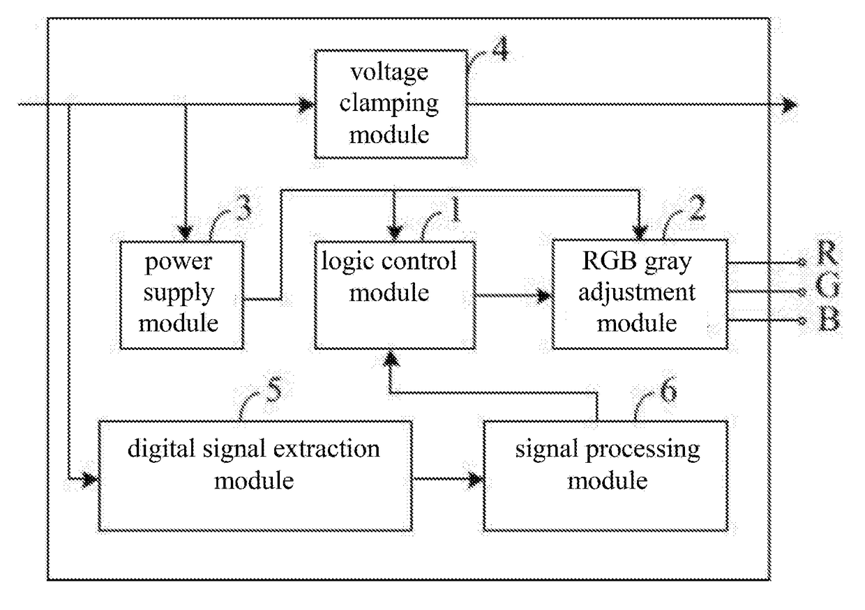
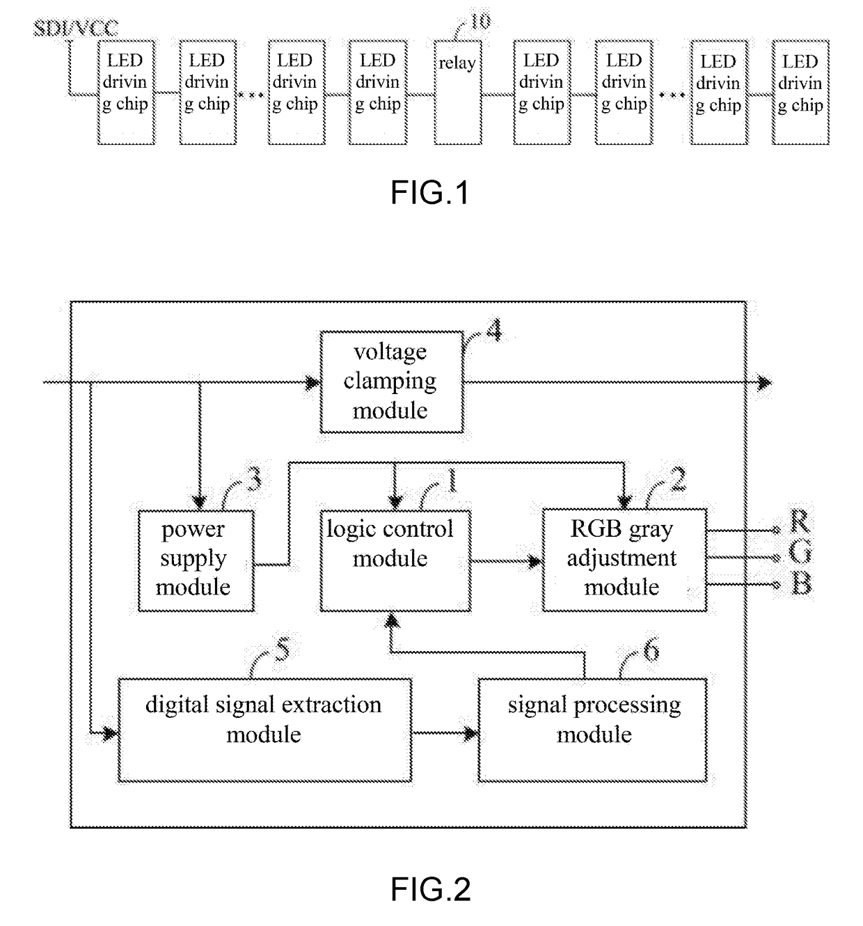
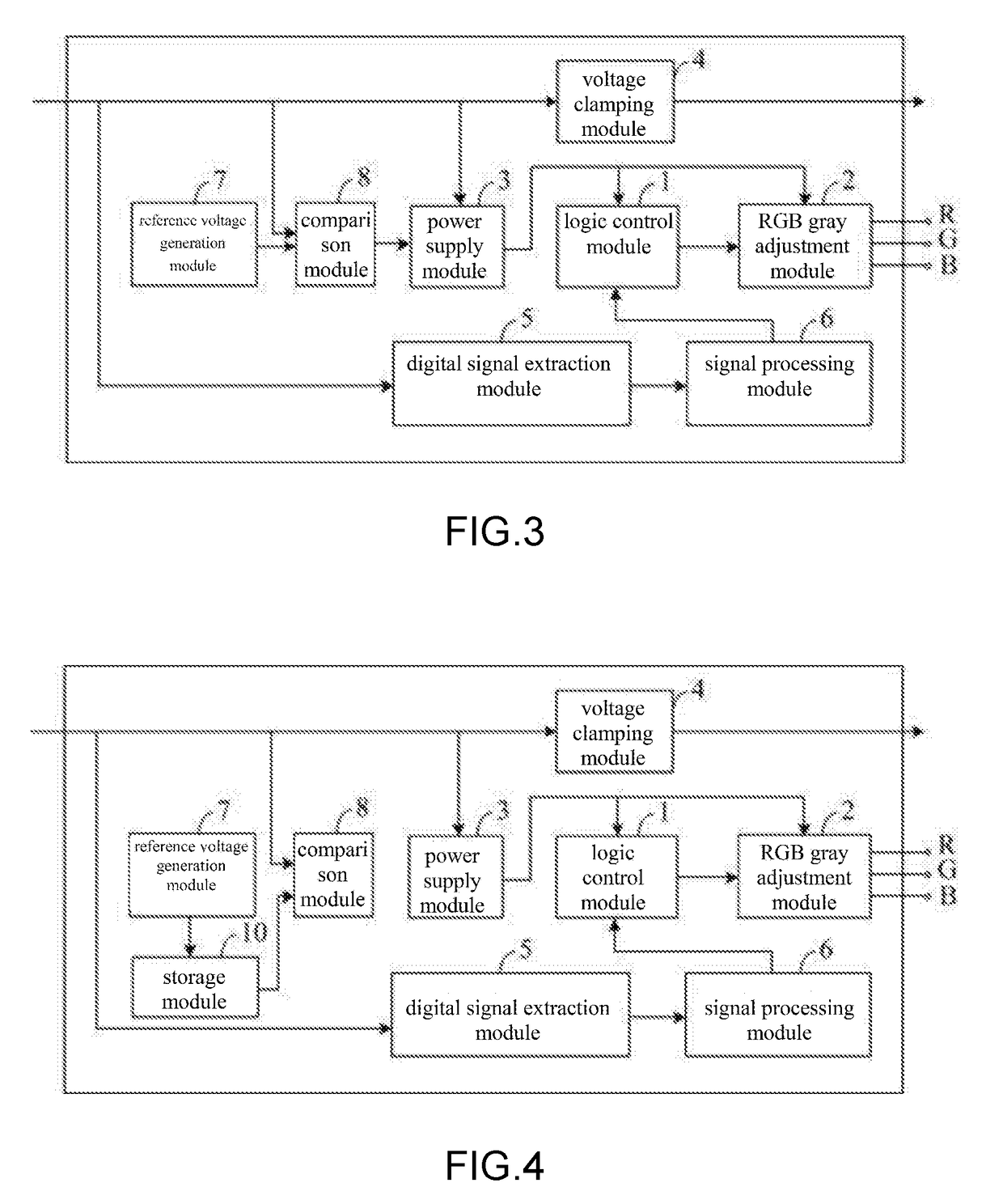
[0021]With reference to FIG. 1 to 5, FIG. 1 is a module chart of the LED driving system with the power transmission path coincided with the data transmission path; FIG. 2 is a module chart of the first embodiment of the LED driving chips of the LED driving system with the power transmission path coincided with the data transmission path; FIG. 3 is a module charge of the second embodiment of the LED driving chips of the LED driving system with the power transmission path coincided with the data transmission path; FIG. 4 is a module charge of the third embodiment of the LED driving chips of the LED driving system with the power transmission path coincided with the data transmission path; FIG. 5 is a module charge of the third embodiment of the LED driving chips of the LED driving system with the power transmission path coincided with the data transm...


PUM


Abstract

An LED driving system with power transmission path coincided with data transmission path, having a plurality of LED driving chips, each having a main input end, a main output end, a logic control module, an RGB gray adjustment module, a power supply module, a voltage clamping module, a digital signal extraction module and a signal processing module. The input end of the voltage clamping module is connected with the main output end of the previous LED driving chip, the output end is connected with the main input end of the next LED driving chip The main input end of the LED driving chip is connected with the digital signal extraction module, which then connects with the signal processing module whose output end is connected with the logic control module which has an output end connected with the RGB gray adjustment module.

Description

BACKGROUND OF THE INVENTION[0001]The invention relates to the technical field of LED driving, in particular to an LED driving system with power transmission path coincided with data transmission path.[0002]In the prior art of application of decorative lights, flexible and hard light bars, LED driving chips are connected in parallel. The chips of all levels are connected in parallel on the same power cord. In this way, the whole system may load with overlarge current, thus making thickness of FPC copper foil increase to some extent and cost of LED products rise.BRIEF SUMMARY OF THE INVENTION[0003]The present invention aims at solving the technical problem of providing an LED driving system that can reduce its current, simplify its wiring, decrease thickness of the FPC copper foil, and save product cost.[0004]The technical scheme of the present invention for solving the aforementioned problem provides an LED driving system with power transmission path coincided with data transmission ...

Claims


Application Information

Patent Timeline
Patent Type & Authority Applications(United States)
IPC IPC(8): H05B37/02H05B33/08H05B44/00
CPCH05B33/0857H05B37/0263H05B45/00H05B45/20H05B47/185H05B45/325H05B45/395
Inventor LIN, FENGCHENGGUO, WANGRUILIN, HAO
Owner DONGGUAN CITY MINLEON ELECTRONICS CO LTD
Learn More