Hybrid standing wave/traveling linear accelerators providing accelerated charged particles or radiation beams

a linear accelerator and standing wave technology, applied in the direction of linear accelerators, accelerators, electrical equipment, etc., can solve the problems of increasing the cost of the linear accelerator system, not always running efficiently, and not always performing, etc., and achieve the effect of high power

Active Publication Date: 2017-09-14
VAREX IMAGING CORP
View PDF2 Cites 13 Cited by
  • Summary
  • Abstract
  • Description
  • Claims
  • Application Information

AI Technical Summary

Benefits of technology

[0029]An RF waveguide may be provided between the RF source and the RF coupler, and a high power circulator may be provided along the RF waveguide to prevent re...

Problems solved by technology

Those familiar with the art are well aware that a linear accelerator is a sophisticated tool that does not always run efficiently, or does not perform at all over such a broad radiation beam operating energy range.
Use of an external focusing system is undesirable because it increases comple...

Method used


Image

  • Hybrid standing wave/traveling linear accelerators providing accelerated charged particles or radiation beams
  • Hybrid standing wave/traveling linear accelerators providing accelerated charged particles or radiation beams
  • Hybrid standing wave/traveling linear accelerators providing accelerated charged particles or radiation beams

Examples


second embodiment

[0056]FIG. 4 is a schematic representation of an example of a hybrid linear accelerator in accordance with the invention, including a parallel RF feed. Items common to FIG. 3 are similarly numbered. The operation and capabilities of this embodiment of the invention are the same as the embodiment of FIG. 3, except as noted herein.

[0057]In this example, the buncher section 110 and the traveling wave section 120 are decoupled by the drift tube 125, as in FIG. 3. The RF source 150 provides RF power through an RF transmitting waveguide 160, via a high power circulator 165, which is then split by an RF splitter 310. A portion of the RF power determined by the dividing ratio of the RF splitter 310 is forwarded through a first arm 315 of the RF splitter to a first RF coupler 320 at the output of the buncher section 110. The remaining power is forwarded through the second arm 330 of the RF splitter 310 to the second input RF coupler 135 through RF switch, RF phase shifter, and / or RF power ad...

third embodiment

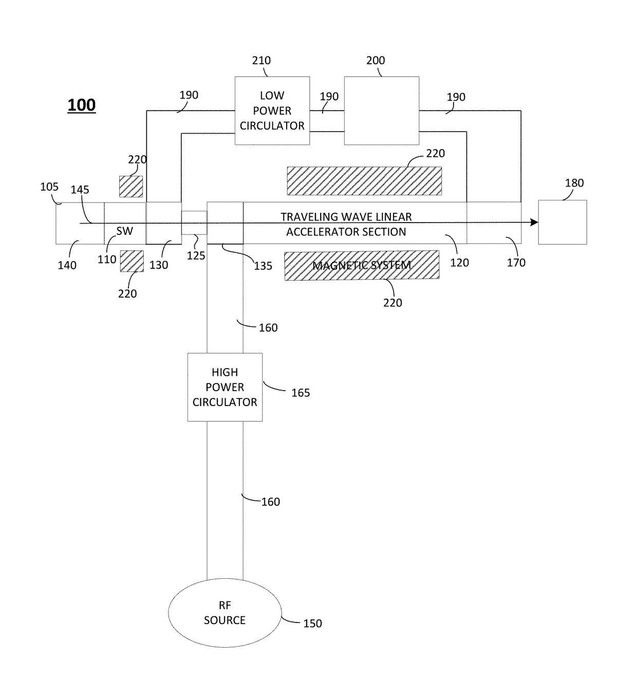
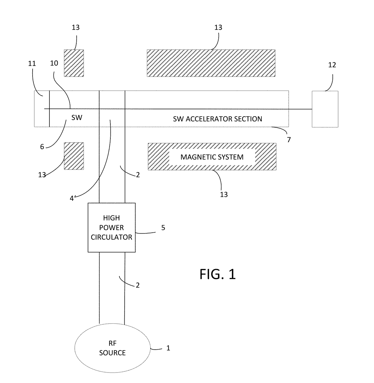
[0061]FIG. 5 is a schematic representation of an example of a hybrid linear accelerator 400 in accordance with the invention. Items common to FIG. 3 are similarly numbered. The operation and capabilities of this embodiment of the invention are the same as the embodiment of FIG. 3, except as noted herein.

[0062]A input RF coupler 410 serves as a combined single RF power input for both the standing wave buncher section 110 and the traveling wave linear accelerator section 120. A drift tube is not provided between the buncher section 110 and the traveling wave section 120 in this embodiment.

[0063]An RF switch 420 may be provided at the RF output of the traveling wave section 120, after an RF coupler 430. The RF switches discussed above may be used here, for example.

[0064]A matched RF load 350, as in FIG. 4, is provided after the radiation beam parameter RF switch 420, to absorb RF power remaining after acceleration in the traveling wave section 120. As above, broad electron energy regul...


PUM


Abstract

A hybrid linear accelerator is disclosed comprising a standing wave linear accelerator section (“SW section”) followed by a travelling wave linear accelerator section (“TW section”). In one example, RF power is provided to the TW section and power not used by the TW section is provided to the SW section via a waveguide. An RF switch, an RF phase adjuster, and/or an RF power adjuster is provided along the waveguide to change the energy and/or phase of the RF power provided to the SW section. In another example, RF power is provided to both the SW section and the TW section, and RF power not used by the TW section is provided to the SW section, via an RF switch, an RF phase adjuster, and/or an RF power. In another example, an RF load is matched to the output of the TW section by an RF switch.

Description

RELATED APPLICATION[0001]The present application is a continuation-in-part of U.S. patent application Ser. No. 15 / 068,355, which was filed on Mar. 11, 2016, is assigned to the assignee of the present invention, and is incorporated by reference herein.FIELD OF THE INVENTION[0002]Embodiments of the invention relates generally to linear accelerators for providing electron beams or x-ray beams, and particularly to such linear accelerators including a standing wave section and a traveling wave section following the standing wave section in a collinear relationship.BACKGROUND OF THE INVENTION[0003]Linear Accelerators (also called “LINACS”) are widely used for a variety of tasks in a broad range of applications, including industrial applications such as Non-Destructive Testing (NDT), Security Inspection (SI), Radiotherapy (RT), electron beam processing —sterilization, and polymer curing, for example. Both accelerated electron beams, and Bremsstrahlung X-ray beam generated by such electron ...

Claims


Application Information

Patent Timeline
IPC IPC(8): H05H9/02H05H7/22H05H7/04H05H9/04H05H7/02
CPCH05H9/02H05H9/04H05H7/02H05H2007/222H05H7/22H05H2007/025H05H2007/041H05H7/04H05H9/042H05H9/047
Inventor MISHIN, ANDREY
Owner VAREX IMAGING CORP
Why Eureka
Try Eureka