Injection needle device for endoscope

Inactive Publication Date: 2017-09-21
KANEKA CORP
View PDF7 Cites 0 Cited by
  • Summary
  • Abstract
  • Description
  • Claims
  • Application Information

AI Technical Summary

Benefits of technology

[0021]The injection needle device for endoscope according to the present invention is configured to have a two-layer structure in which the inner layer is formed on the outer layer of the inner tubular body and to allow drug solution to be in contact with an inner surface of the inner layer, whereby the outer layer can be protected from drug solution. In addition, the outer layer in the present invention has a low water absorption

Problems solved by technology

When the inner tubular body moves relative to the outer tubular body, friction occurs on the cont

Method used


Image

  • Injection needle device for endoscope
  • Injection needle device for endoscope
  • Injection needle device for endoscope

Examples


embodiment

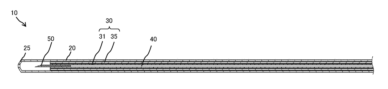
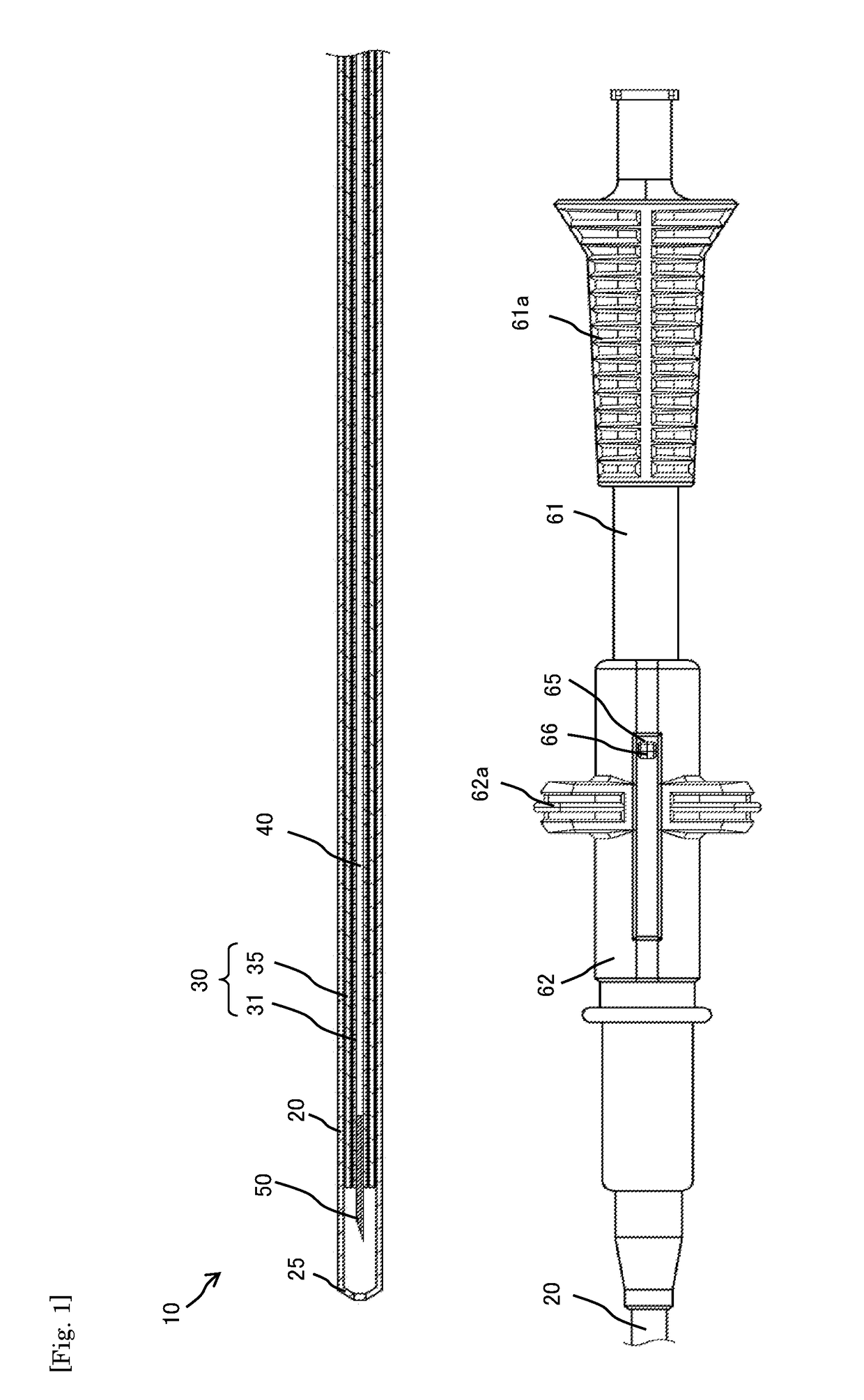
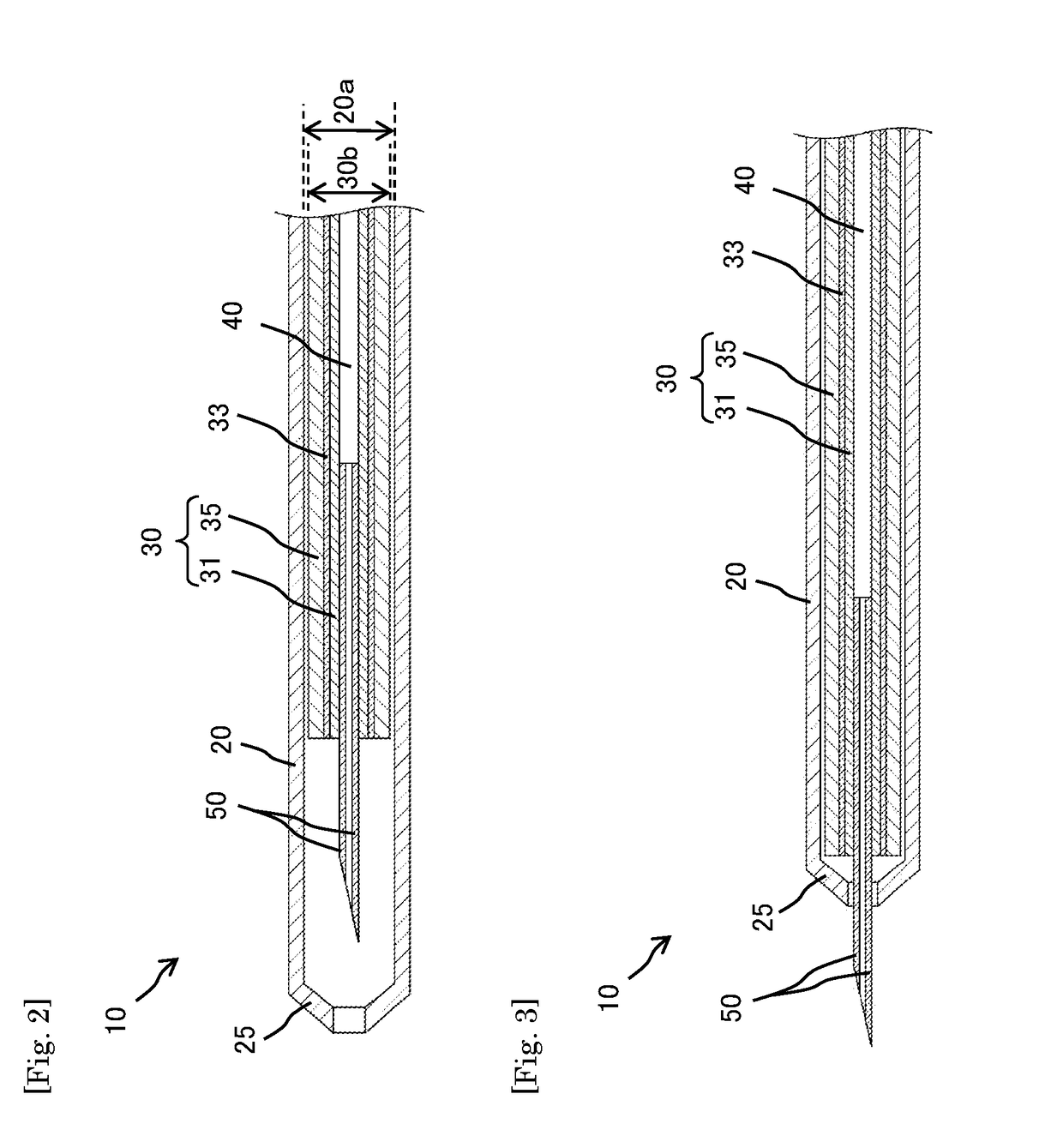
[0054]FIG. 1 shows a plan view (a partial cross-sectional view) of an injection needle device for endoscope 10 in accordance with an embodiment of the present invention, FIG. 2 shows a cross-sectional view taken along an axial direction when an injection needle 50 is stored in an outer tubular body 20 of an injection needle device for endoscope 10 in accordance with the embodiment of the present invention and FIG. 3 shows a cross-sectional view taken along an axial direction when the injection needle 50 is exposed from the outer tubular body 20 of the injection needle device for endoscope 10 in accordance with the embodiment of the present invention. In the injection needle device for endoscope 10, the inner tubular body 30 is provided in the outer tubular body 20 and the injection needle 50 is inserted into one end part of the inner tubular body 30 by thermocompression bonding. The inner tubular body 30 includes an inner layer 31 and an outer layer 35, and the inner layer 31 and th...

examples

[0064]The present invention will be more specifically explained below with reference to specific examples; however, the present invention is not restricted by the below examples and can be put into practice after appropriate modifications within a range meeting the gist of the above and the below, all of which are included in the technical scope of the present invention.

[0065]A test will be described below, in which an amount of change of a position of the tip of an injection needle with respect to an outer tubular body is measured before and after an injection needle device for endoscope is left under a high humidity environment. Firstly, injection needle devices for endoscope needed for the measurement were manufactured, each of the injection needle devices for endoscope including an outer tubular body, an inner tubular body provided in the outer tubular body and having an inner layer and an outer layer, and an injection needle inserted into one end of the inner tubular body. The ...

examples 1 to 3

[0070]In Example 1, after the humidification, the tip of the injection needle was located on the position distant from the end part of the outer tubular body by 2 mm toward the proximal side, and the length in the axial direction of the inner tubular body was 2503 mm. However, the injection needle was not exposed from the outer tubular body. In Example 2, even after the humidification, the tip of the injection needle was still located on the position distant from the end part of the outer tubular body by 5 mm toward the proximal side, and this indicates that the length in the axial direction of the inner tubular body was not changed from 2500 mm. In addition, the injection needle was not exposed from the outer tubular body. In Example 3, after the humidification, the tip of the injection needle was located on the position distant from the distal end part of the outer tubular body by 1 mm toward the distal side, which indicates that the length in the axial direction of the inner tubu...


PUM


Abstract

The present invention provides an injection needle device for an endoscope that can prevent an injection needle from unintentionally being exposed. An injection needle device for an endoscope comprises an outer tubular body (20), an inner tubular body (30) provided in the outer tubular body (20) and an injection needle (50) inserted into one end part of the inner tubular body (30), wherein the inner tubular body (30) includes an inner layer (31) and an outer layer (35) directly or indirectly contacted with an outer surface of the inner layer (31), and a water absorption coefficient of the outer layer (35) is lower than that of the inner layer (31).

Description

TECHNICAL FIELD[0001]The present invention relates to an injection needle device for endoscope for injecting drug solution into a tissue site in a body cavity of a human body through a forceps channel of an endoscope.BACKGROUND ART[0002]An endoscopic surgery is performed, while the state in the body cavity is observed by inserting an endoscope mainly from the mouth, nose, or anus of a patient. In the injection into the body cavity in the endoscopic surgery, an injection needle device for endoscope is inserted into the body cavity of the patient through a forceps channel of the endoscope from a forceps opening of the endoscope, and an injection needle of this injection needle device is inserted into a tissue site of the patient to be treated to inject drug solution thereinto. The injection needle device for endoscope includes an inner tubular body which is for delivering drug solution and has the injection needle provided thereto, and an outer tubular body that stores the injection n...

Claims


Application Information

Patent Timeline
IPC IPC(8): A61M5/32A61L31/04A61L31/06A61B1/018
CPCA61M5/329A61B1/018A61L31/06A61L31/048A61M5/3287A61M5/14
Inventor TSUEDA, MASATO
Owner KANEKA CORP
Why Eureka
Try Eureka