A method for measuring the mass thickness of a target sample for electron microscopy

a target sample and mass thickness technology, applied in the direction of measuring devices, instruments, electric discharge tubes, etc., can solve the problems of inability to measure the x-ray intensities produced in the specimen and the pure bulk element standard using the same beam current, and the x-ray yield of a bulk specimen increases strongly with incident electron energy

Active Publication Date: 2017-09-21
OXFORD INSTR NANOTECH TOOLS
View PDF0 Cites 3 Cited by
  • Summary
  • Abstract
  • Description
  • Claims
  • Application Information

AI Technical Summary

Benefits of technology

[0024]Typically the particle beam at step a) has a first set of beam conditions and the particle beam at step b) has a second set of beam conditions. Preferably, the beam current of the first set of beam conditions is identical to the beam current of the second set of beam ...

Problems solved by technology

However, this is accompanied by a major disadvantage in that the X-ray yield from a bulk specimen increases strongly with incident electron energy.
Therefore, when a pure bulk specimen is exposed to the same electron beam as is used to collect data from the thin specimen, the X-ray intensity, even at minimum beam current, causes an excessive count rate.
Therefore, it is not practical to measure the X-ray intensities produced in the specimen and a pure bulk element standard using the same beam current.
A further issue recognised by Dijkstra et al is that the penetration depth also increases...

Method used


Image

  • A method for measuring the mass thickness of a target sample for electron microscopy
  • A method for measuring the mass thickness of a target sample for electron microscopy
  • A method for measuring the mass thickness of a target sample for electron microscopy

Examples


Embodiment Construction

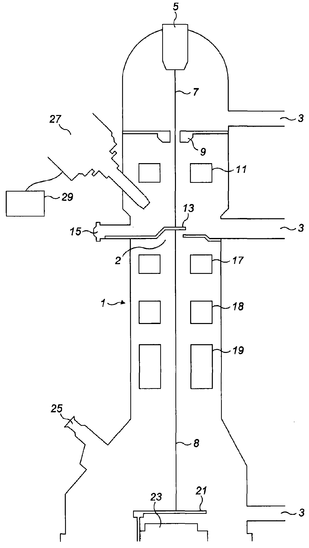
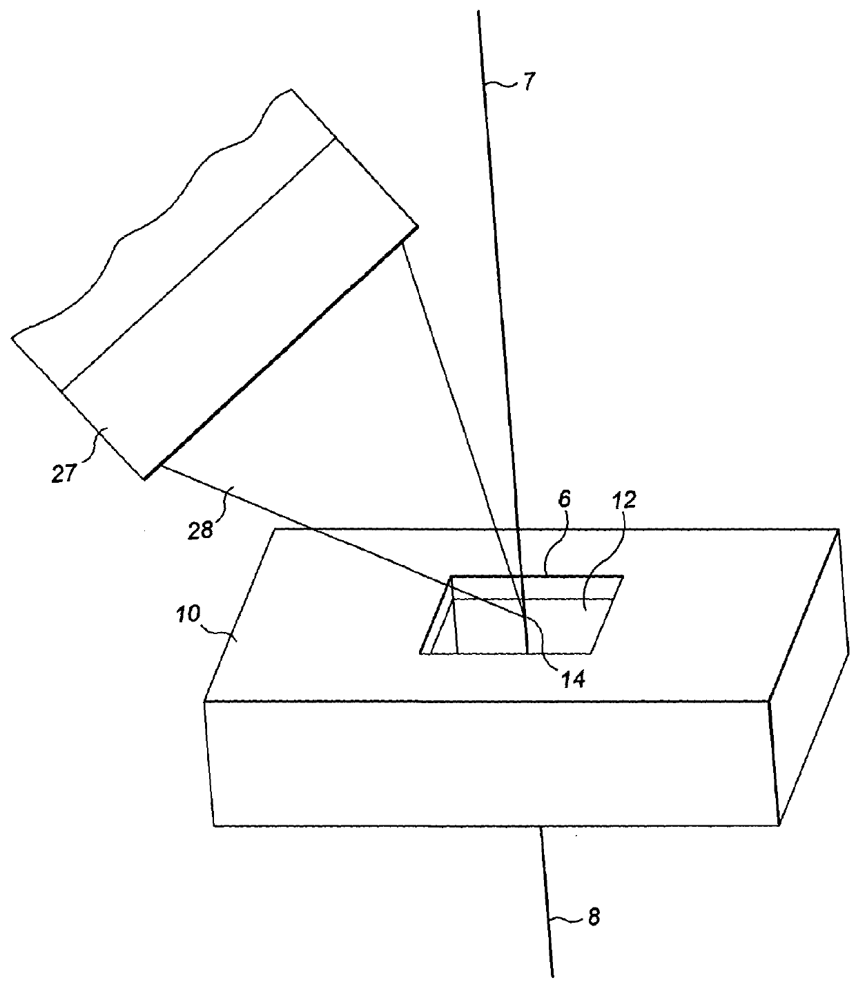
[0041]We firstly describe apparatus suitable for the implementation of the method. A schematic diagram of the apparatus is shown in FIG. 1. This comprises a transmission electron microscope (TEM) 1. As is known in the art a TEM comprises a vacuum chamber 2 evacuated by way of pumping ports 3. The TEM further comprises an electron gun 5 for generating an electron beam 7. The electron beam is drawn from the electron gun along the TEM column by anode 9 and is focussed by condenser lens 11 onto a specimen held by a specimen grid 13. Access for inserting, removing and manipulating the specimen is provided by specimen port 15. Electrons 8 that are transmitted through a thin specimen (sufficiently thin to be partially electron transparent) continue to travel along the TEM column, being focussed by an objective lens 17, intermediate lens 18, and projector lens 19 so as to form an image on imaging plate 21 (essentially a screen). The image is recorded by an image recording device 23, and is ...


PUM


Abstract

A method is provided of measuring the mass thickness of a target sample for use in electron microscopy. Reference data are obtained which is representative of the X-rays (28) generated within a reference sample (12) when a particle beam (7) is caused to impinge upon a region (14) of the reference sample (12). The region (14) is of a predetermined thickness of less than 300 nm and has a predetermined composition. The particle beam (7) is caused to impinge upon a region (18) of the target sample (16). The resulting X-rays (29) generated within the target sample (16) are monitored (27) so as to produce monitored data. Output data are then calculated based upon the monitored data and the reference data, the output data including the mass thickness of the region (18) of the target sample (16).

Description

FIELD OF THE INVENTION[0001]The present invention relates to a method of measuring the mass thickness of a target sample for use in electron microscopy, such as in transmission electron microscopy.BACKGROUND TO THE INVENTION[0002]Specimens for use in a transmission electron microscope (TEM) are prepared so that they are sufficiently thin to allow incident electrons to be transmitted through the specimen so that they can form a high resolution image. The TEM lens conditions can also be modified so that a diffraction pattern can be obtained. In order to achieve a condition wherein the specimen, which is typically less than 200 nm thick in the direction of the electron beam, is electron-transparent, the incident electrons are typically accelerated to energies between 80 keV and 400 keV.[0003]Often such instruments can also be run in a scanning TEM mode (STEM), wherein a finely-focussed spot is deflected in a raster pattern over the specimen and a signal from transmitted or secondary el...

Claims


Application Information

Patent Timeline
IPC IPC(8): G01N23/225H01J37/26
CPCG01N23/2252H01J37/261G01N2223/304H01J2237/24578G01N2223/633
Inventor STATHAM, PETER
Owner OXFORD INSTR NANOTECH TOOLS
Why Eureka
Try Eureka